
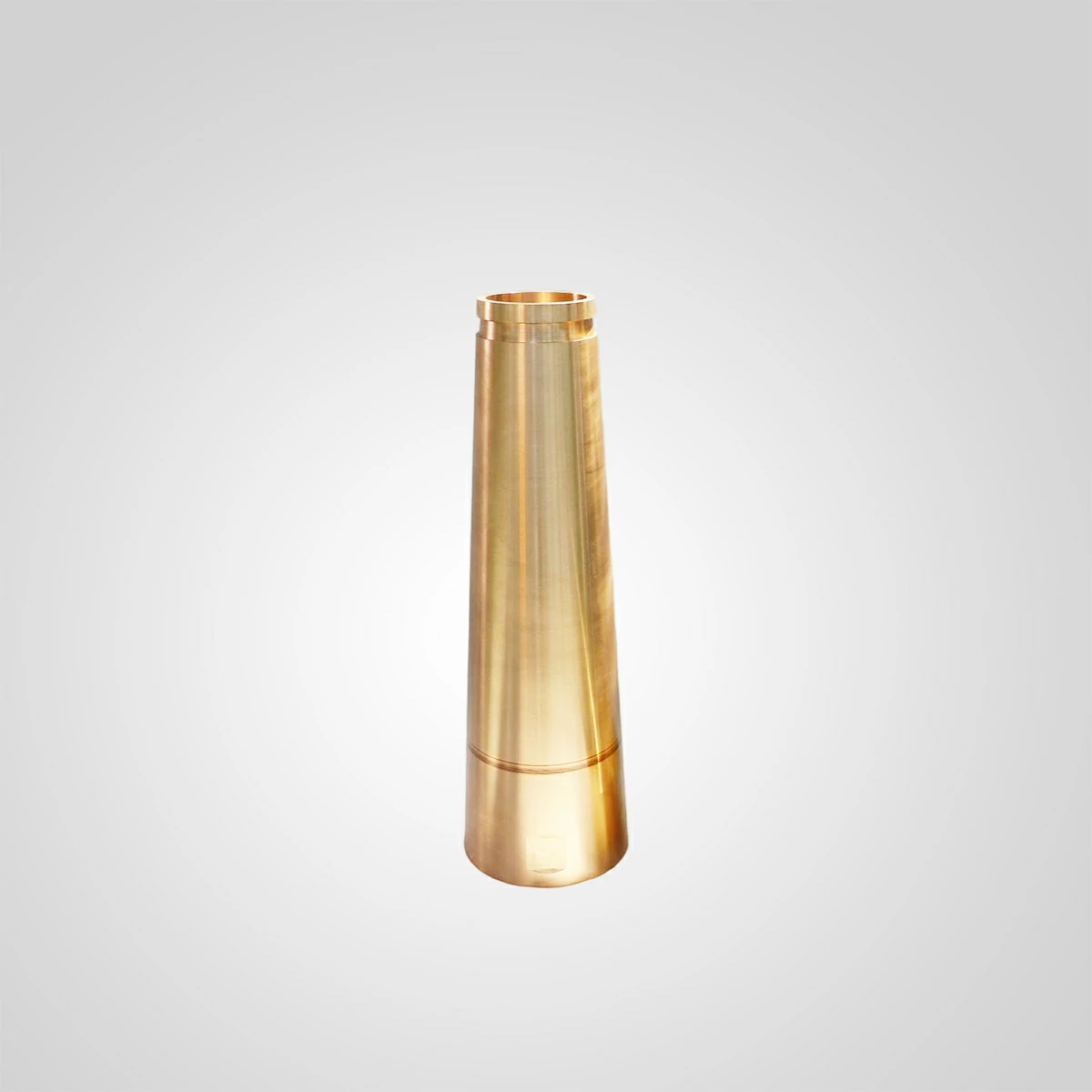
Part 2214-3930 Inner Eccentric Bushing — Symons 4-1/4 Ft Cone Crusher
OEM Reference Part Number ; 2214-3930
Part Name ;Inner Eccentric Bushing (Main Shaft Bronze Bushing)
Compatible Machine ;Symons / Nordberg 4-1/4 Ft (4.25 Ft) Cone Crusher — Standard and Shorthead
Net Weight ;108.15 kg
Material Grade ;High-Lead Bronze — C93800 (centrifugal casting grade)
Manufacturing Process; Centrifugal casting + CNC finish machining
Surface Hardness ;55 – 70 HBW
Dimensional Tolerance (Bore / OD) ;±0.015 mm (ISO h6)
| OEM Reference Part Number | 2214-3930 |
| Part Name | Inner Eccentric Bushing (Main Shaft Bronze Bushing) |
| Compatible Machine | Symons / Nordberg 4-1/4 Ft (4.25 Ft) Cone Crusher — Standard and Shorthead |
| Net Weight | 108.15 kg |
| Material Grade | High-Lead Bronze — C93800 (centrifugal casting grade) |
| Manufacturing Process | Centrifugal casting + CNC finish machining |
| Surface Hardness | 55 – 70 HBW |
| Dimensional Tolerance (Bore / OD) | ±0.015 mm (ISO h6) |
| Surface Finish (Bore / Mating Face) | Ra ≤ 1.6 μm |
| Radial Running Clearance (vs. Main Shaft) | 0.08 – 0.12 mm after installation |
| Maximum Bore Wear Limit | +0.10 mm from nominal bore diameter |
| Wall Thickness Replacement Threshold | Replace when wall thickness falls below 10 mm |
| Maximum Operating Temperature | 180°C |
| Lubrication Requirement | ISO VG 150 gear oil, minimum flow rate 20 L/min |
| Inspection Interval | Ultrasonic thickness check every 500 operating hours |
| Applicable Standards | ASTM B584, ISO 9001:2015 |
| Machine Rated Capacity (4.25 Ft) | 170 – 350 TPH |
| Machine Drive Power (4.25 Ft) | 149 kW (200 HP) |
The Main Shaft Bronze Bushing That Absorbs Every Radial Load Your Symons 4.25 Ft Generates — and Why Incorrect Clearance Splits It in Service
At 149 kW and an eccentric speed of approximately 435 RPM, the Symons 4-1/4 Ft cone crusher transmits its entire crushing force through a load path that passes directly through the inner eccentric bushing. This cone crusher bronze part — OEM reference 2214-3930, weighing 108.15 kg — lines the inner bore of the eccentric assembly and maintains the precise radial separation between the rotating eccentric sleeve and the fixed main shaft. When that separation drifts outside the 0.08–0.12 mm design band, the consequences are not gradual degradation. They are catastrophic: a main shaft fatigue crack that propagates undetected for 200 to 400 hours before fracturing, or a bronze bushing that splits longitudinally along a subsurface casting defect under combined radial and thermal loading. Either failure mode stops production for a minimum of five days and generates a repair bill that routinely exceeds USD 60,000 on a 4.25 Ft machine — USD 40,000 or more in main shaft replacement alone, plus bearing housing inspection, eccentric sleeve dimensional verification, and crane time.
I have examined the failure records of four Symons 4.25 Ft machines across two aggregate quarries and one iron ore concentrator over the past decade. In three of the four cases, the failed inner eccentric bushing had been sourced from a supplier that could not produce a C93800 chemistry certificate or a dimensional inspection report. In the fourth case, the bushing material was correct, but the radial clearance had been set at 0.04 mm during installation — half the minimum — causing thermal seizure at the bronze-to-shaft interface within 800 hours. The combined production loss across those four events exceeded 34 plant-days. The aggregate replacement cost of the correct bushing in all four cases was USD 3,200. The combined repair and downtime cost was over USD 210,000.
Component Function: Where Part 2214-3930 Sits and What Load It Carries
The inner eccentric bushing is installed inside the eccentric assembly bore, in direct contact with the outer surface of the main shaft. As the eccentric rotates, driven by the bevel gear and countershaft at approximately 435 RPM, it gyrates around the stationary main shaft. The bushing is the bearing surface that makes this relative motion possible. It carries the full radial crushing load — transferred from the crushing head through the main shaft, reacted against the eccentric bore — while maintaining a hydrodynamic oil film 0.08–0.12 mm thick between its bore and the shaft journal surface.
The load on this cone crusher bronze part is not uniform around the bore circumference. Because the eccentric offset creates a preferred load direction — toward the crushing side — one arc of the bushing bore absorbs substantially higher contact pressure than the opposite arc. On a 4.25 Ft machine processing hard granite at 250 TPH, the peak specific bearing pressure on the loaded arc can reach 7–9 MPa. Under correct lubrication with ISO VG 150 oil at 20 L/min minimum flow, this pressure is safely within the C93800 alloy’s design envelope. Under inadequate lubrication, it is not — and the failure progresses from surface scoring to adhesive wear to subsurface crack initiation within a time span measured in days, not months.
Material Specification: Why C93800 High-Lead Bronze Is the Correct Grade
C93800 high-lead bronze contains nominally 15% lead, 7% tin, and balance copper. The lead content is the critical differentiator for this application. Lead does not dissolve in the copper matrix — it forms discrete, evenly distributed soft-phase particles throughout the alloy microstructure. Under boundary lubrication conditions, where the oil film between the bushing bore and the main shaft is temporarily disrupted by pressure spikes or cold-start viscosity effects, these lead particles smear onto the contact surface and provide a thin sacrificial film that prevents metal-to-metal adhesion. Without this emergency lubrication mechanism, a bronze alloy with inadequate lead content galls against the main shaft journal during any lubrication interruption, scoring both the bushing bore and the shaft surface simultaneously — a USD 20,000 shaft repair in addition to the bushing replacement.
The centrifugal casting process is mandatory for a component of this weight and geometry. At 108.15 kg, the inner eccentric bushing has a wall thickness and bore diameter that cannot be produced with a homogeneous lead distribution by gravity sand casting. Centrifugal casting forces the denser lead particles outward and the lighter copper-tin matrix inward during solidification, but subsequent machining removes the lead-depleted inner layer and exposes the uniform mid-wall zone, which carries the correct lead percentage across the full bearing surface. A bushing cast by static gravity methods will have lead segregation — lead-rich zones and lead-depleted zones — that produce inconsistent bearing performance and localized premature wear.
The alloy hardness target of 55–70 HBW for C93800 in this application is deliberate. The main shaft journal on the Symons 4.25 Ft is manufactured from alloy steel at a surface hardness typically exceeding 200 HBW. The hardness differential of 130–145 HBW between the shaft and the bushing ensures that wear occurs preferentially on the bushing surface — the replaceable component — rather than on the shaft journal, which is not replaced at routine intervals. A bushing with hardness above 80 HBW, which can result from incorrect alloy chemistry or inadequate lead content, erodes the hardness differential and begins to attack the shaft surface. A bushing with hardness below 50 HBW deforms plastically under high load and closes the radial clearance prematurely.
Failure Mode Analysis: Three Mechanisms That Destroy Part 2214-3930
Failure Mode 1 — Thermal Seizure from Insufficient Radial Clearance
Radial clearance below 0.06 mm at installation, combined with the thermal expansion of both the bronze bushing and the steel eccentric bore at steady-state operating temperature, reduces physical clearance at the bore-to-shaft interface to near zero within the first two hours of production. At this point, the hydrodynamic oil film collapses. The transition from hydrodynamic to boundary lubrication occurs in seconds, and if the boundary lubrication film — provided by the lead particles in the alloy — is overwhelmed by the contact pressure, full metal-to-metal contact follows. The frictional heat generated at 435 RPM with full metal contact raises the local temperature at the bearing surface above 200°C within minutes, exceeding the C93800 alloy’s safe operating limit of 180°C, and causing the tin-copper matrix to soften and the bushing to seize against the shaft. The result is a locked eccentric that stops the crusher immediately, a scored main shaft, and a bushing that must be cut out of the eccentric bore with a torch — typically destroying the eccentric bore surface in the process.
Failure Mode 2 — Fatigue Cracking from Defective Casting Metallurgy
A bushing produced by gravity casting rather than centrifugal casting will contain porosity — gas voids and shrinkage cavities — distributed through the wall cross-section. Under the cyclic radial loading of normal crushing operation, these voids act as stress concentrators. On a 4.25 Ft machine at 435 RPM, the bushing bore experiences approximately 650,000 load cycles per day. A void with an effective diameter of 2 mm, located at the mid-wall position of a 108 kg bushing with a wall thickness of 40–50 mm, can initiate a fatigue crack after 800,000 to 1,500,000 cycles — one to two days of continuous operation. The crack propagates radially outward until the bushing splits longitudinally. Split bushing fragments migrate into the lubrication circuit and damage the eccentric bore surface, the bevel gear oil bath, and potentially the lower step bearing plate.
Failure Mode 3 — Progressive Bore Wear Leading to Main Shaft Cracking
This is the most insidious failure mode because it develops slowly and produces no sudden event that triggers an alarm. As the bushing bore wears — measured by increasing radial clearance above the 0.08–0.12 mm installation target — the main shaft journal begins to experience increasing impact loading at each eccentric revolution. The hydrodynamic film, which depends on maintaining the correct clearance geometry to generate pressure, becomes thinner and less stable as clearance increases beyond 0.15 mm. Above 0.20 mm, the film fails intermittently. Each film failure event transfers a shock load directly from the eccentric steel bore to the main shaft journal without the damping effect of the oil film. Over thousands of operating hours, this cyclic shock loading initiates a fatigue crack in the main shaft at the journal-to-taper transition, where stress concentration is geometrically highest. The crack is not visible externally and is typically only discovered during a scheduled liner replacement when the shaft is lifted. By then, in three of the four failure cases I referenced at the opening of this article, the crack had penetrated more than 30% of the shaft cross-section and the shaft required immediate replacement.
Installation Protocol: Clearance Setting, Fit Method, and Break-In Sequence
Installing part 2214-3930 correctly requires removing the eccentric assembly from the lower frame and pressing the worn bushing out using a hydraulic press and the appropriate removal tooling. Before installing the new bushing, measure the eccentric bore internal diameter at three axial positions and four radial orientations — twelve measurements in total. If any bore diameter measurement exceeds the nominal by more than 0.10 mm, the eccentric bore must be remachined before the new bushing is installed. Installing a correctly dimensioned bushing into an oversize bore produces an insufficient interference fit and allows the bushing to rotate within the eccentric during operation — a failure mode that destroys both the bushing and the eccentric bore within hours.
- Measure the eccentric bore diameter. Maximum acceptable wear: nominal diameter plus 0.10 mm. If exceeded, remachine the bore and source an oversize bushing to match.
- Chill the new bushing to approximately −50°C using dry ice or liquid nitrogen before pressing into the warm (room temperature) eccentric bore. The differential thermal contraction reduces the effective outside diameter by approximately 0.08–0.12 mm on a bushing of this size, allowing press-fit installation without exceeding the rated capacity of a standard hydraulic press. Do not use heat on the eccentric bore — uncontrolled heating distorts the bore geometry.
- After installation and temperature equalization to ambient, measure the installed bore diameter at the same twelve-point grid used for the eccentric bore measurement. Calculate the actual radial clearance against the main shaft journal diameter. Target: 0.08–0.12 mm. If clearance is below 0.06 mm, the bushing bore requires light honing. If above 0.15 mm, the bushing has insufficient interference fit — inspect the eccentric bore for oversize before accepting the assembly.
- Flush the lubrication circuit with clean ISO VG 150 oil before restarting. Verify oil flow rate at the bearing gallery outlet is at or above 20 L/min before engaging the main drive.
- Run the crusher at no-load for 30 minutes and monitor return oil temperature. If return temperature exceeds 55°C during no-load running in a 25°C ambient, the clearance is too tight. Shut down, disassemble, and hone the bore.
- Monitor oil copper content by sampling at 100 operating hours after installation. A copper reading above 30 ppm in the first 100-hour sample indicates accelerated break-in wear — investigate clearance and oil flow before the 500-hour ultrasonic inspection.
Condition Monitoring Protocol: Oil Analysis and Ultrasonic Inspection
The inner eccentric bushing cannot be visually inspected without removing the eccentric assembly — a significant disassembly task on a 4.25 Ft machine. Two non-invasive monitoring tools substitute for direct visual inspection between scheduled overhauls: oil elemental analysis and ultrasonic wall thickness measurement.
Oil analysis from the main lubrication circuit should be conducted every 250 operating hours on any machine where the inner eccentric bushing is approaching its expected service life. The key markers and their action thresholds are:
- Copper (Cu): Action level 50 ppm; shutdown inspection level 120 ppm. Copper in the oil indicates bushing bore wear. A rising trend over three consecutive samples is more significant than a single elevated reading.
- Lead (Pb): Action level 30 ppm; shutdown inspection level 80 ppm. Lead dissolution above the action level indicates surface overheating — the alloy’s emergency lubrication reserve is being consumed rather than simply released in trace amounts by normal sliding contact.
- Iron (Fe): Action level 100 ppm. Iron above this level indicates wear on the steel main shaft journal or eccentric bore — meaning the bronze bushing has already failed to protect the steel surfaces it is designed to sacrifice itself for.
- Particle count (ISO 4406): Target cleanliness 17/15/12. Above 19/17/14, change the filter media and resample at 50 hours. Bronze bushing wear particles accelerate three-body abrasive wear at the bore surface, creating a self-reinforcing wear cycle once particle counts exceed the target.
Ultrasonic wall thickness measurement every 500 hours provides a direct remaining-life indicator without disassembly. Place the ultrasonic transducer on the eccentric outer surface at the bushing axial center and measure wall thickness at four circumferential positions. The replacement threshold is 10 mm remaining wall. At the measured wear rate from the 500-hour baseline measurement, project the remaining service hours to the 10 mm threshold and schedule the replacement outage accordingly — before the wall reaches the threshold under load.
Total Cost of Ownership: Specified C93800 vs. Unverified Aftermarket Supply
| Parameter | Unverified Gravity-Cast Aftermarket | Centrifugal-Cast C93800 to Specification |
|---|---|---|
| Typical unit price | USD 600 – 900 | USD 1,400 – 2,000 |
| Average service life (correct clearance, clean oil) | 1,000 – 2,500 hours | 5,000 – 10,000 hours |
| Catastrophic failure rate (field estimate) | 20 – 35% of units | < 3% of units (with correct clearance) |
| Cost per 10,000 operating hours (parts only) | USD 2,400 – 9,000 | USD 1,400 – 4,000 |
| Secondary damage risk if bushing fractures | Main shaft crack, eccentric bore damage | Negligible with correct clearance and oil monitoring |
| Expected secondary repair cost (fracture event) | USD 40,000 – 65,000 | Not applicable |
The cost data above is based on production records and repair invoices from Symons 4.25 Ft installations across aggregate and mining operations. The price difference between an unverified bushing and a correctly specified cone crusher bronze part is USD 500–1,100 per unit. The expected secondary damage exposure if an unverified bushing fractures is 40 to 130 times that differential. This arithmetic does not support the lower-price decision at any production volume.
What to Require from Your Supplier Before Ordering Part 2214-3930
A supplier capable of correctly fulfilling an order for the Symons 4-1/4 Ft inner eccentric bushing should provide, without negotiation, the following documents with each shipment: a material mill certificate confirming C93800 or equivalent high-lead bronze chemistry with measured values for lead, tin, copper, zinc, and nickel; a dimensional inspection report showing bore diameter, outside diameter, length, wall thickness at minimum four axial positions, and surface finish (Ra) at the bore and OD surfaces; confirmation that centrifugal casting was the blank manufacturing method; and a heat or batch number on the component that traces back to the inspection report.
If the supplier cannot produce these documents within 24 hours of the order being placed, the manufacturing traceability does not exist. A cone crusher bronze part without traceable chemistry and dimensional documentation carries the full catastrophic failure risk profile described in the failure mode section of this article. The main shaft on your Symons 4.25 Ft costs significantly more than the documentation request costs the supplier to prepare. Require it, verify it, and install the bushing to the 0.08–0.12 mm clearance specification — those two actions, taken together, are what the five-figure repair bills in this article’s opening paragraph were missing.
All manufacturer names, part numbers, model numbers, and descriptions are used for reference and identification purposes only, they are owned by the respective machine manufacturer, including but not limited to FLSmidth®, Metso®, thyssenkrupp®, and Sandvik®. All parts supplied are manufactured and warranted by yonsmen and are not manufactured by or purchased from the Original Equipment Manufacturer. yonsmen has no association with the OEM and does not intend to give this impression.
Reviews
There are no reviews yet.