

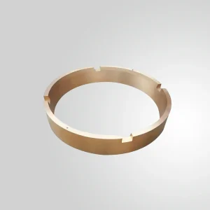
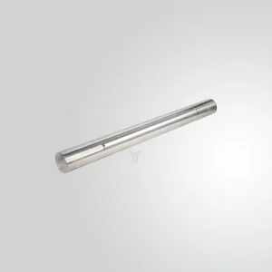
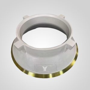
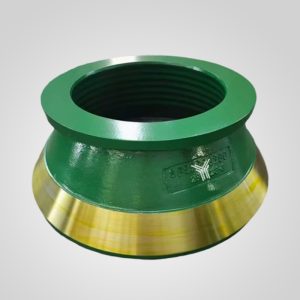
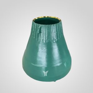
77016200123 Counter Weight Counterweight 77016200123 for HP500 Cone Crusher Stone Cone Crusher Machine Portable
Component Name :Counterweight Assembly
OEM Part Number :77016200123
Applicable Machine :HP500 Multi-Cylinder Hydraulic Cone Crusher
Main Body Material :Heavy-Duty Ductile Iron (QT500-7)
Internal Ballast Core: 99.9% Pure Industrial Lead
Tensile Strength :≥ 500 MPa
Yield Strength: ≥ 320 MPa
Hydro-Pneumatic Kinematics: The Evolution of High-Capacity Rock Reduction
A multi-cylinder hydraulic cone crusher subjects its foundation to dynamic loads routinely exceeding five times its static mass during peak operational phases. Unlike legacy spring-loaded systems, these high-performance machines utilize a pressurized hydraulic network to maintain the main shaft position, lock the bowl assembly, and provide instantaneous tramp iron release. The mechanical tolerances required to sustain this level of crushing force are microscopic. A deviation of mere millimeters in the foundation plane or a slight contamination in the hydrodynamic lubrication system will initiate a rapid cascade of component failure, beginning with eccentric bushing degradation and ending with a catastrophic main shaft fracture. Consequently, the installation and commissioning phases of these crushers demand an extreme level of engineering precision, far surpassing traditional aggregate equipment standards.
Material Composition Analysis: Wear Components and Structural Integrity
The transition from spring-compression crushers to multi-cylinder hydraulic platforms necessitates a massive upgrade in metallurgical standards. The sheer compressive forces exerted during choke feeding require specific alloy compositions to prevent premature plastic deformation or catastrophic brittle fracture.
| Component Type | Material Grade | Yield Strength (MPa) | Performance Profile and Field Application |
| Mantle & Bowl Liner (Standard) | Mn14Cr2 | 350 | Standard austenitic manganese steel. Work-hardens under impact. Suitable for medium-hard limestone and non-abrasive ores. |
| Mantle & Bowl Liner (Heavy Duty) | Mn18Cr2 or Mn22Cr2 | 420 – 480 | High-manganese matrix heavily alloyed with chromium. Exceptional work-hardening capacity for highly abrasive silica and granite. |
| Main Frame & Adjustment Ring | Cast Steel ZG270-500 | 270 | Provides the necessary tensile strength to withstand continuous radial stretching forces without permanent dimensional distortion. |
| Dynamic Ballast | Ductile Iron with Lead Core | 320 | High mass-to-volume ratio. Essential for absorbing kinetic energy and maintaining strict dynamic equilibrium along the rotational axis. |
Precision Field Installation Protocol
The physical erection of a multi-cylinder hydraulic crusher is a multi-stage process governed by strict metrological verification. Ignoring structural tolerances during this phase guarantees severe operational vibration and drivetrain fatigue.
- Foundation and Lower Frame Verification: The reinforced concrete foundation must cure to its maximum compressive rating before accepting the lower frame. Field engineers must verify the foundation elevation, centerline alignment, and anchor bolt coordinates, ensuring all deviations fall strictly within a 3 mm tolerance. When hoisting the lower frame onto the concrete pad, leveling is critical. Using highly sensitive machinist levels across the upper machined flange, the frame must be shimmed until the horizontal deviation is less than 0.1 mm per 1000 mm. Once achieved, secondary non-shrink epoxy grouting must be poured and allowed to cure for a minimum of seven days.
- Eccentric Assembly and Rotational Balancing: The installation of the transmission shaft and the eccentric rotating mass dictates the machine’s vibration signature. To achieve absolute dynamic balance, integrating the exact Counter Weight Counterweight 77016200123 for HP500 Cone Crusher Stone Cone Crusher Machine Portable ensures the offset mass neutralizes the violent centrifugal forces generated by the crushing head. The backlash between the pinion and the bevel gear must be verified using lead wire or Prussian blue, ensuring full flank contact.
- Spherical Bearing and Main Shaft Insertion: Prior to dropping the moving cone assembly, the spherical bearing seat and the internal threads of the main shaft must be heavily coated with an extreme-pressure molybdenum disulfide grease. The hoist must lower the main shaft with absolute verticality to prevent scoring the bronze eccentric bushing. Once seated on the spherical bearing, the moving cone must rotate freely by hand.
- Hydraulic Clamping and Tramp Release Systems: The upper fixed cone assembly, comprising the bowl liner, adjustment ring, and lock ring, relies on an array of hydraulic clamping cylinders. These cylinders must be piped with absolute cleanliness. Any silica dust or pipe scale entering the hydraulic manifolds will instantly score the directional valves, causing the clamping ring to slowly back off during operation, which inevitably strips the massive adjustment threads.
| Technical Parameter | Specification & Standard |
| Component Name | Counterweight Assembly |
| OEM Part Number | 77016200123 |
| Applicable Machine | HP500 Multi-Cylinder Hydraulic Cone Crusher |
| Main Body Material | Heavy-Duty Ductile Iron (QT500-7) |
| Internal Ballast Core | 99.9% Pure Industrial Lead |
| Tensile Strength | ≥ 500 MPa |
| Yield Strength | ≥ 320 MPa |
| Dynamic Balance Standard | Compliant with ISO 1940 Grade G6.3 High-Precision Dynamic Balancing |
| Bore Assembly Tolerance | ± 0.05 mm (Ensures precise interference/clearance fit with the eccentric sleeve) |
| Operating Temperature Range | -20°C to +65°C (Dependent on baseline lubricating oil and U-seal integrity) |
[Option C: Field Case Snippet]: The Cost of Ignoring Hydrodynamic Cleanliness
In the summer of 2023, I was called to audit a newly commissioned aggregate plant in Nevada struggling with a 400-horsepower multi-cylinder machine. Within the first 150 hours of operation, the main lube system repeatedly triggered high-temperature alarms, ultimately shutting down the plant. The on-site contractors had bypassed the critical pre-start flushing procedure. When I pulled the return line filters, they were packed with microscopic weld slag and paint chips from the newly installed piping. This debris had bypassed the primary filtration, entered the eccentric assembly, and acted as a lapping compound, destroying a $15,000 inner bronze bushing in less than a week. We had to tear down the entire machine, replace the bronze components, and run the independent lubrication station for 12 straight hours through temporary kidney-loop beta filters until the ISO cleanliness codes dropped to acceptable limits. It was a half-million-dollar mistake caused by skipping a fundamental installation step.
Commissioning Sequence and Hydrodynamic Calibration
The startup sequence of a multi-cylinder hydraulic machine operates on a strict hierarchy: auxiliary systems first, prime mover second; no-load mapping first, progressive load testing second.
- Phase 1: Lubrication and Hydraulic Verification: Fill the lubrication reservoir with premium synthetic ISO VG 150 or 220 oil, depending on ambient conditions. The lubrication pump must run independently for 2 to 4 hours. During this phase, verify that the supply pressure stabilizes between 0.1 and 0.2 MPa. The return oil temperature should slowly climb and stabilize. Simultaneously, energize the hydraulic station, pressurize the clamping cylinders, and perform a simulated tramp iron release test to ensure the accumulator bladders react instantaneously to pressure spikes.
- Phase 2: Unloaded Rotational Baseline: Jog the main drive motor to confirm proper rotational direction, which is almost exclusively clockwise when viewed from the drive sheave. Run the crusher completely empty for a minimum of two hours. Engineers must monitor the coast-down time once the power is cut; a rapid deceleration indicates severe internal friction and an improperly seated bearing. The main motor amperage should remain flat and well below the nameplate rating.
- Phase 3: The Mandate of Choke Feeding: The fundamental operating principle of a multi-cylinder unit is inter-particle comminution, which only occurs under choke-fed conditions. Begin loading the chamber at 30% capacity, ensuring the rock stream completely buries the distribution plate. Run for 45 minutes to allow the thermal profile to normalize. Gradually ramp the feed rate to 70%, closely monitoring the motor amperage. Finally, increase the feed until the chamber is entirely full (choke fed) and the main motor operates consistently at 90% to 95% of its rated full-load amperage. Starve-feeding this machine will result in erratic bouncing of the adjustment ring, massive oversized product, and highly localized wear on the manganese liners.
Advanced Preventive Maintenance Guidelines
Transitioning from reactive repair to predictive asset management is mandatory for these high-capital machines. The physical tolerances inside the crushing chamber dictate the overall efficiency of the entire downstream circuit.
- Tribological Oil Analysis: Implement a strict 250-hour oil sampling protocol. Monitor the parts-per-million (PPM) of copper, lead, and tin. A sudden spike in lead indicates the boundary lubrication layer is failing and the bronze eccentric bushing is experiencing active metal-to-metal contact. Track the ISO cleanliness codes to ensure the labyrinth dust seals have not been compromised by silica ingress.
- Hydraulic Accumulator Pre-Charge Verification: The nitrogen pre-charge in the hydraulic accumulators must be verified monthly. If the nitrogen bladders lose pressure, the hydraulic system loses its compressibility. Consequently, when an un-crushable piece of steel enters the chamber, the hydraulic fluid has nowhere to go, resulting in burst hoses, fractured tie rods, or a cracked main frame.
- Closed-Side Setting (CSS) Drift Monitoring: Record the hydraulic adjustment ring position daily. As the manganese liners wear, the system must thread the bowl downward to maintain the target product size. Tracking this daily drift allows maintenance planners to accurately predict the remaining lifespan of the liners and schedule replacement shifts without interrupting production quotas.
Frequently Asked Questions (FAQ)
1. Why is the secondary concrete grouting so critical during the initial frame installation?
The primary anchor bolts are designed to handle tensile vertical loads, not severe lateral shear forces. The high-strength secondary epoxy grout fills every void between the machined underside of the crusher frame and the concrete foundation. This solid mass transfers the massive horizontal kinetic energy generated by the crushing action directly into the earth, preventing the anchor bolts from snapping under cyclic fatigue.
2. What causes the main drive motor to draw highly erratic amperage during a load test?
Erratic amperage is almost always a symptom of “starve feeding” or severe feed segregation. If the material is trickling into the chamber, or if all the large rocks are falling to one side, the crushing head experiences massive, uneven shock loads rather than a steady, continuous crushing pressure. You must utilize a variable frequency drive (VFD) on your feeder to maintain a continuous, buried crushing cavity.
3. How often should the synthetic oil in the primary lubrication station be completely replaced?
While the exact interval depends on your oil analysis reports, a general baseline for a heavy-duty multi-cylinder crusher operating in a dusty quarry environment is every 2,000 operating hours. However, if the oil cooler ruptures and introduces water into the system, or if a dust seal fails and introduces silica, the entire oil volume must be replaced immediately to prevent catastrophic bearing failure.
4. If the crusher stalls on a piece of tramp metal, how is the chamber safely cleared?
Modern multi-cylinder hydraulic machines feature an automated clearing function. You must cut power to the main drive and the feeder immediately. Using the hydraulic control panel, actuate the tramp release sequence, which depressurizes the clamping cylinders and forces hydraulic fluid into the clearing cylinders, lifting the entire upper frame and bowl assembly. This instantly widens the discharge opening, allowing the jammed metal to drop through the bottom.
5. What precautions must be taken when transporting the moving cone and main shaft assembly?
The main shaft and moving cone assembly represent a massive, top-heavy load with highly fragile machined surfaces. It must be transported vertically on a custom-built wooden or steel cradle that supports the underside of the crushing head. The highly polished main shaft must be wrapped in heavy corrosion-inhibiting material and protected by a rigid steel sleeve to prevent any impact damage from rigging chains or adjacent cargo during transit.
All manufacturer names, part numbers, model numbers, and descriptions are used for reference and identification purposes only, they are owned by the respective machine manufacturer, including but not limited to FLSmidth®, Metso®, thyssenkrupp®, and Sandvik®. All parts supplied are manufactured and warranted by yonsmen and are not manufactured by or purchased from the Original Equipment Manufacturer. yonsmen has no association with the OEM and does not intend to give this impression.
Reviews
There are no reviews yet.