The Bull Gear in FLSmidth Cone Crushers: Function, Failure, Replacement, and Preventive Maintenance
A 4,500-hour run-to-failure on an FLSmidth Raptor XL900 ended not with a worn mantle or a cracked concave, but with a catastrophically spalled bull gear that took the pinion shaft bearing housing with it. The repair bill exceeded $280,000 USD — roughly six times what a properly scheduled gear replacement would have cost. That incident, which I witnessed firsthand at a copper concentrator in northern Chile, is the single most instructive lesson I can offer anyone responsible for managing these crusher parts. The bull gear is not a glamorous component, but it is the mechanical heart of the eccentric drive system, and neglecting it follows a very predictable and expensive script.
What the Bull Gear Does: Power Transmission at the Core of the Eccentric Assembly
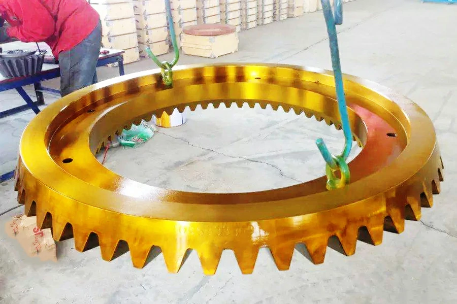
In every FLSmidth cone crusher — whether a legacy Symons 7-Foot Standard or a modern Raptor XL1100 — the bull gear (also called the large bevel gear) performs one irreplaceable mechanical function: it receives rotational torque from the countershaft pinion and redirects it 90 degrees to drive the eccentric sleeve. This directional change is what causes the main shaft to gyrate rather than simply rotate, generating the compressive crushing motion that fractures rock between the mantle and concave liners.
The bull gear is a spiral bevel gear, and its design must simultaneously handle high radial loads, moderate axial thrust, and cyclical impact loading every time an uncrushable tramp iron event occurs. On a Raptor XL900, the bull gear operates under a continuous transmitted torque of approximately 85 kN·m at rated speed (485 RPM countershaft), with instantaneous peak torques during tramp events reaching 2.5 to 3 times that figure. These are not theoretical values — they are the design parameters that govern material selection for these crusher parts.
Material Specification and Metallurgical Requirements
FLSmidth specifies the bull gear blank as a forged alloy steel conforming to ASTM A668 Class F or equivalent DIN 17210 standards, with a minimum tensile strength of 830 MPa and a yield strength of no less than 585 MPa. After rough machining, the gear undergoes carburizing and case hardening to achieve a tooth flank surface hardness of 58–62 HRC at a case depth of 2.0–3.5 mm, while the core retains a toughness-oriented hardness of 300–360 HBW. This dual-hardness profile is deliberate: the hard case resists pitting and surface fatigue (Hertzian contact stress on the Raptor XL900 tooth flanks runs approximately 1,100–1,300 MPa), while the tough core absorbs impact energy without brittle fracture.
The finished tooth flank surface roughness must meet Ra ≤ 0.8 μm, and the tooth profile tolerance falls within AGMA Quality Grade 10 or ISO 1328 Class 5. Deviations outside these tolerances produce uneven load distribution across the tooth face width (typically 220–260 mm on large Raptor frames), which accelerates micropitting — a failure mode that begins invisibly and announces itself only when surface material begins to flake away in irregular patches.
Primary Failure Modes: How Bull Gears Actually Die
Micropitting and Spalling
Micropitting initiates when the elastohydrodynamic (EHL) oil film between mating tooth surfaces breaks down, typically because the lubricant viscosity grade is incorrect for the operating temperature. On FLSmidth crushers running in ambient temperatures above 35°C, using an ISO VG 220 gear oil instead of the specified ISO VG 320 reduces film thickness ratio (Lambda ratio) below 1.0, placing the contact in boundary lubrication. Once micropitting covers more than 10% of the active tooth flank, spalling follows within 500–800 operating hours.
Scoring and Galling
Galling — severe adhesive wear that transfers metal from one tooth surface to the other — typically results from incorrect backlash. The specified backlash for Raptor series bull gears ranges from 0.38 mm to 0.64 mm depending on frame size. I have measured backlash as tight as 0.18 mm on field-installed aftermarket gears, a condition that generates flash temperatures at the tooth contact zone high enough to break down the EP additive package in the gear oil within weeks.
Bending Fatigue at the Tooth Root
Repeated overloads — particularly from wet, clay-packed feed that causes bowl float — introduce bending stress cycles at the tooth root fillet. If the fillet radius is undersized (below R2.5 mm on standard Raptor tooth profiles), a stress concentration factor above 1.8 applies, and root cracks propagate within the high-cycle fatigue regime. This failure mode typically produces a clean, transgranular fracture surface and can result in complete tooth loss.
Replacement Decision Criteria
The decision to replace the bull gear should not wait for visible tooth damage. A structured inspection protocol using the following thresholds keeps the replacement of these crusher parts planned rather than emergency-driven:
- Tooth flank pitting covering more than 4% of the active contact zone on any single tooth
- Measured pitch error (composite error) exceeding 0.15 mm over a full revolution
- Backlash worn to less than 0.25 mm or greater than 0.90 mm
- Oil particle count from the eccentric oil circuit exceeding ISO 4406 Code 21/19/16 on two consecutive monthly samples
- Vibration spectrum showing a gear mesh frequency (GMF) sideband amplitude increase of more than 6 dB above baseline
Field Case Snippet: In 2019, I consulted on an FLSmidth 52-75 gyrasphere at a gold operation in Western Australia. The maintenance team had been tracking a rising GMF at 1× and 2× since the previous shutdown, but deferred replacement because the gear “looked fine” visually. When we pulled it at the next planned stop, the subsurface fatigue cracks were already 8–11 mm deep into three consecutive teeth. Two more weeks of operation would have produced a catastrophic failure during a shift. Visual inspection alone is simply not sufficient for this category of crusher parts.
Bull Gear Replacement: Step-by-Step Field Procedure
Step 1: Lockout/Tagout and Preparation
Implement full LOTO per MSHA 30 CFR Part 47 or site-equivalent standard. Drain the eccentric oil reservoir completely — do not attempt to work around residual oil. Remove the feed hopper, main frame upper assembly, and head assembly per the FLSmidth disassembly sequence to expose the main frame lower assembly.
Step 2: Eccentric Assembly Extraction
Using the FLSmidth hydraulic extraction tooling (or an approved equivalent hydraulic press with a minimum capacity of 150 tonnes on large frames), apply a steady extraction force to the eccentric bushing. Record the extraction force — values significantly above the specified range (typically 60–120 tonnes for Raptor XL900) indicate bushing seizure and may require thermal assistance at no more than 120°C applied uniformly.
Step 3: Bull Gear Removal
The bull gear is secured to the eccentric hub via a series of high-tensile bolts (Grade 10.9, M36 or M42 depending on frame size). Using a calibrated torque wrench or hydraulic tensioner, release the bolts in a star pattern. The specified removal torque is typically 60–70% of the installation torque to avoid thread galling. Lift the gear vertically using a lifting beam attached to the gear’s integrated lifting provisions — never use chains over the gear teeth.
Step 4: Seating Surface Inspection and Preparation
Inspect the eccentric hub mating face for fretting corrosion. Surface flatness must be within 0.05 mm over the full contact diameter. Any high spots must be carefully dressed with a precision flat file and verified with a calibrated straight edge. Apply Molykote G-Rapid Plus or Loctite LB 8012 anti-seize compound to the mating face at a film thickness of 0.03–0.05 mm before fitting the new gear.
Step 5: New Gear Installation and Torque
Lower the replacement bull gear — a genuine OEM component or a certified equivalent manufactured to AGMA 6013 Class I standards — onto the hub using the lifting beam. Align the timing marks if present. Install the Grade 10.9 fasteners by hand, then torque in three stages using a star pattern: 30%, 60%, and finally 100% of the specified value. For M42 Grade 10.9 bolts, the final torque is 3,500 N·m. After full torque is achieved, apply a witness mark across each bolt head and the gear face to detect any loosening during initial run-in.
Step 6: Backlash Setting and Verification
After reassembling the eccentric assembly and countershaft, measure the bull gear-to-pinion backlash using a dial indicator mounted tangentially to the bull gear pitch circle. Rotate the countershaft by hand and record the total indicator reading (TIR). Adjust the countershaft bearing housing position (via shim adjustment) to achieve backlash within the specification band: 0.38–0.51 mm for Raptor XL500 and XL700 frames; 0.51–0.64 mm for Raptor XL900 and XL1100 frames.
Pro-Tip: I always perform backlash measurement at three angular positions of the bull gear — 0°, 120°, and 240° — not just one. Runout in a poorly manufactured aftermarket gear can produce backlash variation of 0.15 mm or more around the circumference, a condition that causes a distinctive “once-per-revolution” vibration signature and accelerated pinion wear. I have rejected three different low-cost gear sets on this basis alone over the past decade.
Preventive Maintenance: Oil Analysis and Lubrication Management
The single highest-return maintenance practice for prolonging bull gear life is a monthly oil analysis program on the eccentric lubrication circuit. The key parameters and their action thresholds are as follows:
| Parameter | Baseline (New Oil) | Warning Threshold | Action Threshold |
|---|---|---|---|
| Iron (Fe) content | < 10 ppm | 40–80 ppm | > 100 ppm |
| Chromium (Cr) content | < 2 ppm | 8–15 ppm | > 20 ppm |
| Particle count (ISO 4406) | 17/15/12 | 19/17/14 | 21/19/16 |
| Kinematic viscosity @ 40°C | 320 cSt ± 10% | ±15% deviation | ±20% deviation |
| Water content | < 0.05% | 0.10–0.20% | > 0.20% |
A rising iron trend combined with stable chromium typically indicates bushing wear rather than gear wear. A simultaneous rise in both iron and chromium is a strong indicator of tooth surface degradation. When chromium spikes to above 20 ppm within a single sample interval, accelerated tooth inspection at the next opportunity is mandatory — do not wait for the next scheduled shutdown.
OEM vs. Low-Cost Aftermarket: A Full-Cycle Cost Analysis
The acquisition price of a genuine FLSmidth bull gear for a Raptor XL900 is substantial — typically in the range of $28,000–$36,000 USD depending on configuration and lead time. Low-cost aftermarket alternatives are available from various suppliers at 40–55% of that price point, and the purchasing argument is superficially attractive. However, a total cost of ownership (TCO) analysis over a 3-year operating cycle consistently reverses the economics:
| Cost Category | OEM-Standard Crusher Parts | Low-Cost Aftermarket |
|---|---|---|
| Initial component cost | $32,000 | $15,000 |
| Average service life | 18,000–22,000 hours | 6,000–9,000 hours |
| Replacements over 3 years (6,000 hr/yr) | 1 | 2–3 |
| Associated pinion wear cost | Low (matched geometry) | High (profile mismatch) |
| Unplanned downtime risk (est. cost) | Low — $15,000/event est. | High — $80,000+/event est. |
| Estimated 3-year TCO | $47,000 | $110,000–$185,000 |
The driving factor in this comparison is not component longevity alone, but profile accuracy. A bull gear manufactured outside AGMA Quality Grade 10 generates 15–30% higher dynamic loads on the pinion at rated speed, which cascades into premature pinion bearing failure and eccentric bushing wear — both of which are expensive crusher parts in their own right. The apparent savings on the gear itself are typically consumed by collateral damage within the first replacement cycle.
Recommended Maintenance Intervals
- Every 500 hours: visual inspection of accessible gear flanks through the inspection port; check oil level and temperature at eccentric housing; record backlash if accessible without disassembly
- Every 1,000 hours: oil sample submitted for spectrometric analysis; vibration spectrum captured at all four bearing housings and compared to baseline
- Every 4,000 hours (or at major liner change): full disassembly inspection of bull gear and pinion; measure tooth profile with gear tooth vernier or CMM; replace oil regardless of analysis result
- Every 8,000–10,000 hours: consider proactive replacement of bull gear and pinion as a matched set, regardless of measured condition, as part of a zero-unplanned-downtime strategy
Conclusion: Treating the Bull Gear as a System Component
The bull gear does not fail in isolation. It fails as part of a system — a system that includes the pinion, the eccentric bushing, the lubricating oil, the drive motor loading, and the feed conditions presented to the crusher every shift. Managing these crusher parts effectively means treating the bull gear not as a commodity to be purchased cheaply and replaced reactively, but as a precision-manufactured power transmission element whose condition reflects the health of the entire eccentric drive train. When the oil analysis is trending, the vibration data is telling a story, and the inspection port reveals early pitting — those are the moments that define whether your next shutdown is planned or catastrophic. After more than two decades working on these machines across four continents, I can confirm that the mines that get this right are the ones that treat their data as seriously as they treat their ore grade.