When a Jaw Plate Develops a Crack at 06:00: The Cost of Delayed Inspection
A 300mm x 1200mm fixed jaw plate operating at 250 RPM under continuous quarry feed generates peak impact stresses routinely exceeding 180 MPa per crushing cycle. When a hairline fracture forms in the Mn14Cr2 manganese matrix and goes undetected for even 48 hours, the crack propagates under cyclic fatigue at an accelerating rate. By the time the plate fractures catastrophically, the shockwave is powerful enough to shear the toggle pin, distort the pitman body, and score the flywheel keyway. A comprehensive, systematic approach to inspecting, servicing, and testing jaw crusher parts is not an optional maintenance task. It is the single most effective intervention that separates a plant running at 95% availability from one haemorrhaging money on emergency welding crews and expedited freight for replacement components.
Phase One: Systematic Wear Inspection of Core Jaw Crusher Parts
Before a single wrench is lifted, a disciplined visual and dimensional inspection must be completed. The objective is to identify both catastrophic failure and sub-critical wear that will become catastrophic within the next maintenance interval.
Fixed and Swing Jaw Plate Condition Assessment
The jaw plates are the primary wear components absorbing the full kinetic energy of the crushing process. Standard heavy-duty jaw plates are cast from Mn18Cr2 austenitic manganese steel, which conforms to ASTM A128 Grade E-1. This alloy achieves its remarkable wear resistance not from initial hardness, but from work-hardening during service. The surface Brinell hardness of a new Mn18Cr2 plate starts at approximately 200 HBW. Under continuous rock impact, the surface layer cold-works to a hardness of 450 to 550 HBW while the core remains tough at 200 HBW, absorbing energy without brittle fracture. This dual-phase behavior is the fundamental mechanism that makes manganese steel the dominant choice for jaw crusher parts worldwide.
During inspection, the plate profile must be measured with a straight-edge rule and a depth gauge. The tooth crest height of a new corrugated plate is typically 60 to 80 mm. Once the crest wears to less than 15 mm, the plate has lost its ability to grip and fracture feed material efficiently, resulting in increased power consumption and a coarser product size distribution. Beyond profile wear, any transverse crack wider than 2 mm or extending more than 60% through the plate cross-section constitutes a mandatory replacement condition, regardless of remaining tooth height.
[Option C: Field Case Snippet]: The Crack That Hid Behind the Wear Profile
During a scheduled 500-hour overhaul at a granite quarry in 2022, I pulled the fixed jaw plate from a 900 x 1200 jaw crusher to find a crack running cleanly from the top mounting bolt hole toward the center tooth, approximately 340 mm long. The crack was invisible from the feed side because the rock had compacted fine dust into the fracture line, masking its depth. When I used a magnetic particle test kit, the full extent of the crack lit up immediately. The operator had reported nothing unusual. The plate was operating at just under 1,000 hours and the wear profile looked acceptable. If I had passed on the NDT inspection and re-installed that plate, the next feed surge would have split it in two. Replacing the plate during a scheduled window cost 6 hours of planned downtime. A catastrophic fracture under load would have cost 72 hours minimum, plus pitman damage.
Toggle Plate, Toggle Seats, and Discharge Setting
The toggle plate is a precision-engineered sacrificial safety component. It is intentionally designed as the weakest structural link in the drivetrain, rated to fracture under impact loads that would otherwise destroy the pitman, eccentric shaft, or mainframe. However, the toggle seats — the hardened steel or manganese pads on which the toggle plate rests — are subject to slow fretting wear and compressive deformation. If the toggle seat radius does not precisely match the toggle plate end radius, contact stress concentrates on a narrow band, initiating a Hertzian fatigue crack on both mating surfaces.
Inspect the toggle seat contact surface for spalling, which presents as small, shallow craters of material loss on the contact face. Any spalling indicates that the contact geometry is no longer full-width. Measure the toggle clearance — the gap between the toggle plate ends and the seats — using a feeler gauge. The OEM specification for most mid-size jaw crushers falls between 0.10 and 0.25 mm. A clearance below 0.05 mm indicates the seat has deformed and is creating localized point loading that will fracture the toggle plate prematurely, even under normal operating loads.
Discharge Setting Verification
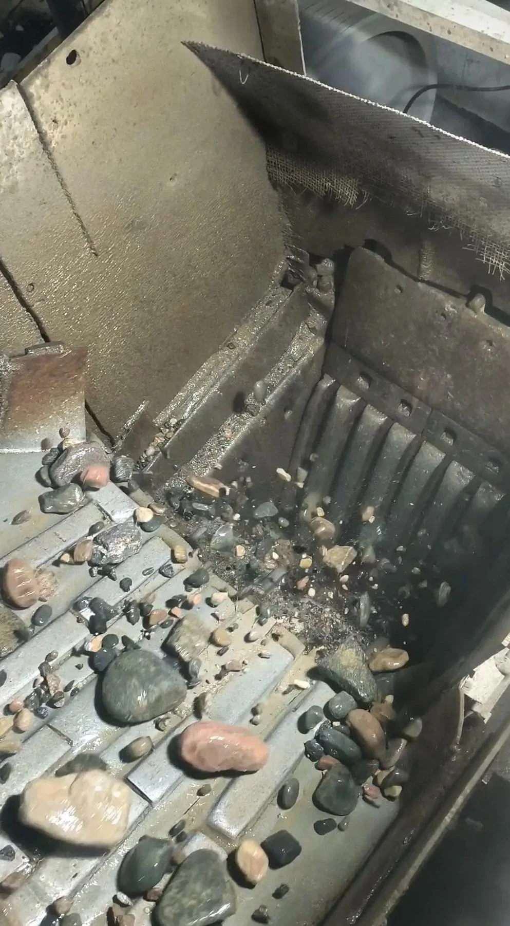
The discharge opening, or closed-side setting (CSS), directly controls product size and throughput. Adjust the CSS by adding or removing toggle wedge shims. On machines with a hydraulic adjustment system, verify the piston seal integrity before making any hydraulic corrections. Lead pellets dropped through the crushing cavity provide a reliable and direct physical measurement of the CSS. Use three pellets simultaneously, dropped at the left edge, center, and right edge. A deviation of more than 5 mm between the left and right measurement indicates the swing jaw is deflecting under load, suggesting a worn pitman bearing or a bent pitman body.
Phase Two: Eccentric Shaft Bearing Lubrication and Inspection Protocol
The eccentric shaft bearings are the highest-stress dynamic components in a jaw crusher. A 900 x 1200 machine will have a main eccentric shaft with a journal diameter of approximately 200 to 250 mm, and the operating surface speed on the bearing interface exceeds 2.5 m/s. These bearings operate in the boundary-to-mixed lubrication regime, meaning the oil film is never fully continuous. The continuous collapse and reformation of the hydrodynamic film under the impact loading imposes extreme demands on both the lubricant viscosity index and the bronze bushing alloy.
Standard eccentric shaft bushings for heavy-duty jaw crusher parts are manufactured from C93800 high-leaded tin bronze, which provides a Brinell hardness of approximately 55 to 65 HBW on the bearing surface. Crucially, the bearing surface finish must meet Ra ≤ 1.6 μm. A finish rougher than this tears apart the nascent hydrodynamic oil film, causing accelerated adhesive wear on both the bronze bushing and the hardened steel journal.
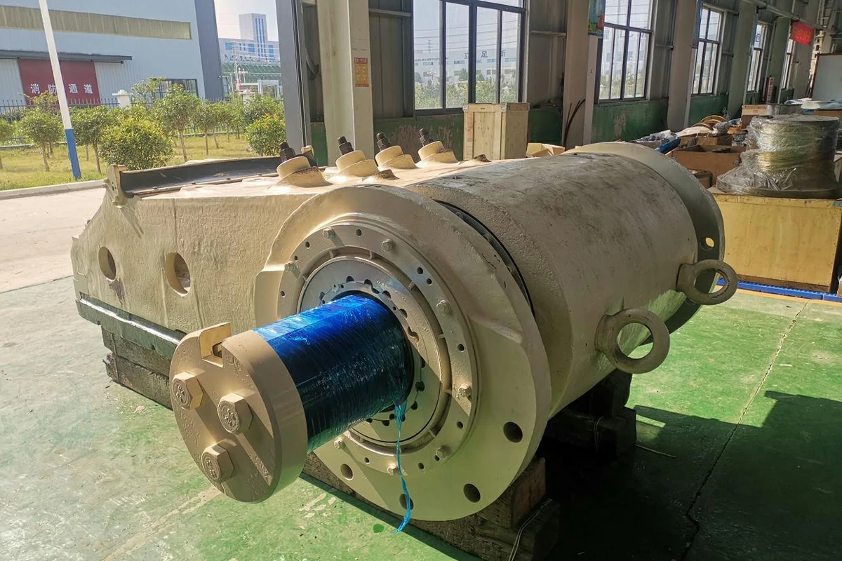
During maintenance, drain the bearing housings and inspect the drained oil for copper and tin particles. A concentration of copper exceeding 30 PPM in a standard oil analysis sample indicates active adhesive wear on the C93800 bushing surface. Refill with the OEM-specified viscosity grade. For most quarry environments operating between 10°C and 40°C ambient temperature, an ISO VG 220 mineral oil with a high-pressure additive package is the standard specification.
[Option B: Pro-Tip]: The Grease Purge Method for Sealed Pillow Block Bearings
On machines using sealed rolling element bearings on the eccentric shaft ends rather than full sleeve bushings, I always purge the bearing fully rather than simply adding grease. To do this, I remove the relief plug on the opposite side of the grease nipple, apply the grease gun, and pump until fresh, clean grease begins to push out through the relief hole. This process physically displaces all the contaminated, compacted grease from the bearing cavity. Failing to do this simply packs more grease on top of silica-contaminated grease, which turns the inside of the bearing into a lapping compound. I have seen this single habit extend bearing service life from 800 hours to over 2,500 hours on identical machines in the same quarry.
Phase Three: Reassembly Torque Standards and Operational Readiness
After all jaw crusher parts have been inspected, adjusted, or replaced, the reassembly sequence requires strict torque compliance. Jaw plate retaining bolts, typically M36 or M42 Grade 10.9 high-tensile hardware, must be torqued in a cross pattern across the full plate face. The specified torque for an M36 Grade 10.9 bolt in this application is approximately 2,500 Nm. Using a calibrated hydraulic torque wrench is mandatory, as standard breakover torque wrenches at this range carry a calibration uncertainty of up to 15%, which is insufficient for a structural fastener carrying 180 MPa impact loads.
| Component | Material Standard | Key Specification | Replacement Trigger |
| Fixed Jaw Plate | Mn18Cr2 / ASTM A128 Grade E-1 | Initial Hardness: 200 HBW; Work-hardened peak: 550 HBW | Tooth height below 15 mm or any crack over 60% through section |
| Swing Jaw Plate | Mn18Cr2 / ASTM A128 Grade E-1 | Initial Hardness: 200 HBW; Work-hardened peak: 550 HBW | Asymmetric profile wear exceeding 20 mm deviation across width |
| Toggle Plate | Grey Cast Iron or UHMW Polymer (sacrificial) | Tensile Strength: 250 MPa (designed to fracture under overload) | Any visible crack or fracture, regardless of length |
| Eccentric Shaft Bushing | C93800 High-Leaded Tin Bronze | Surface Finish: Ra ≤ 1.6 μm; Hardness: 55 to 65 HBW | Copper PPM over 30 in oil analysis, or bore wear exceeding ±0.15 mm |
| Jaw Plate Retaining Bolts | Grade 10.9 Alloy Steel (M36 or M42) | Torque: 2,500 Nm (M36); Never reuse if previously shock-loaded | Any evidence of thread galling, stretch, or reduced torque retention |
Phase Four: No-Load and Loaded Operational Run-In Testing
Following full reassembly, a structured run-in test is mandatory before the machine is returned to production duty. Jog the main drive motor for three seconds and confirm the correct rotation direction. Then run the machine empty for 30 minutes. During this period, listen for any rhythmic metallic knocking synchronized with the eccentric rotation, which indicates an improperly seated toggle plate or a loose jaw plate. Measure bearing housing temperature with an infrared thermometer at the 15-minute and 30-minute marks. A rise above 70°C at 30 minutes in ambient conditions of 25°C signals an over-packed bearing housing or a marginal running clearance on the eccentric bushing.
Once the no-load test is satisfactory, begin the loaded run-in test with clean, uniform feed material at approximately 40% of the designed tonnage rate. Monitor the main motor amperage on the control panel display. The no-load amperage for a 110 kW jaw crusher is typically 15 to 20 amps. A stable loaded amperage at 40% feed rate should sit around 40 to 50% of the full-load amperage rating. Listen for the characteristic steady, uniform sound of layer-by-layer particle fracture. Any sudden pops, metallic impacts, or a rhythmic change in the crushing sound requires an immediate shutdown and a secondary inspection of the toggle seat area and the jaw plate mounting hardware.
After 60 minutes of successful loaded operation, increase the feed rate to the designed operational tonnage and monitor for one final hour. Record the motor amperage, bearing temperatures, and the product particle size distribution. If all parameters fall within the OEM design specifications, the overhaul is complete and the machine is cleared for full production. These jaw crusher parts, properly maintained and installed to specification, are capable of operating for 1,200 to 1,800 hours before the next scheduled inspection interval, keeping the plant running at maximum availability and minimum cost per tonne.