A cone crusher may continue operating for several shifts with partially worn liners. It will not operate for long after the oil film around its eccentric bushing collapses. Although copper-alloy components do not directly break the rock, they control the alignment, lubrication, heat transfer, and running clearance of the entire crushing system.
This is why a crusher bushing should never be treated as an ordinary replacement sleeve. It is a precision bearing component operating under high radial loads, intermittent impact, oil contamination, temperature changes, and continuous sliding motion. A machining error of only a few hundredths of a millimetre can change the contact pattern, interrupt the lubricant film, and accelerate damage to the eccentric, main shaft, or frame.
In practical maintenance work, the cost of the bushing itself is rarely the main concern. The greater risk is the secondary damage caused by an incorrectly manufactured or installed component. A low-cost bushing can become an extremely expensive crusher wear part when it damages a shaft, eccentric assembly, or main frame.
Crusher Copper Parts Are Usually Copper Alloys, Not Pure Copper
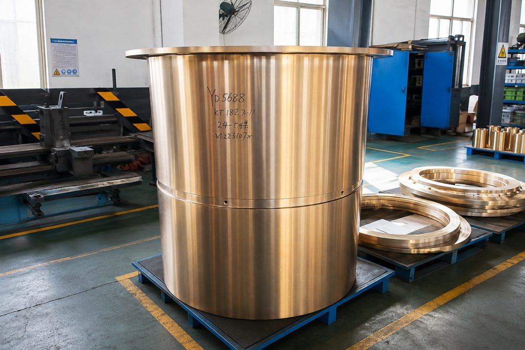
The term “copper part” is commonly used at crushing plants, but most crusher bushings are manufactured from engineered copper alloys rather than pure copper. Depending on the crusher design and operating load, the material may be tin bronze, leaded bronze, aluminium bronze, or another OEM-specified bearing alloy.
These alloys are selected because they combine load-carrying capacity, conformability, embeddability, corrosion resistance, and emergency running performance. A properly selected bronze alloy can tolerate minor shaft misalignment and capture small contamination particles before those particles score a more expensive steel surface.
However, a harder alloy is not automatically better. Excessive hardness may reduce conformability and transfer wear to the shaft. An alloy that is too soft may deform, close the oil clearance, or develop edge loading. Material selection must therefore match the shaft hardness, lubricant viscosity, operating temperature, crusher speed, and expected bearing pressure.
What a Crusher Bushing Actually Does
1. Maintains shaft and eccentric alignment
The bushing supports rotating or oscillating components and keeps their movement within the designed centreline. When the internal diameter becomes tapered or oval, the shaft no longer runs concentrically. The result may include uneven liner wear, abnormal vibration, unstable power draw, and local heating.
2. Creates a controlled hydrodynamic oil film
During normal operation, the shaft should not continuously rub directly against the bronze surface. Rotation draws lubricant into the clearance and creates a pressurised oil wedge. This film separates the two surfaces and carries the load.
The oil film depends on several connected variables: running clearance, oil viscosity, rotational speed, bearing load, surface finish, groove position, and oil temperature. Increasing clearance without engineering approval does not necessarily improve lubrication. Excessive clearance reduces oil-film pressure, increases shaft movement, and can produce impact loading at every revolution.
3. Transfers frictional heat
Bronze conducts heat away from the loaded area into the surrounding structure and lubricant. If the oil flow is restricted or the contact area is concentrated on one edge, heat generation exceeds heat removal. The first symptoms are often a rising return-oil temperature, darkened lubricant, bronze particles in the filter, or an unusual odour near the lubrication station.
4. Protects more expensive crusher parts
A bushing is designed to be replaceable. The main shaft, eccentric, and frame bore are not. In this sense, the bushing functions as a sacrificial precision component. It should wear gradually and predictably while protecting the surrounding steel crusher parts.
Typical Technical Control Points
Exact acceptance limits must come from the crusher manufacturer’s drawing or service manual. The following values are practical reference ranges for supplier evaluation and workshop inspection; they must not override model-specific OEM requirements.
| Inspection Item | Typical Reference | Why It Matters |
|---|---|---|
| Bearing surface roughness | Commonly Ra 0.8–1.6 μm after final machining | A surface that is too rough breaks the oil film; an excessively polished surface may retain insufficient lubricant during start-up. |
| Hardness | Often approximately 65–120 HB, depending on the specified bronze alloy | Confirms heat treatment and alloy condition. The correct value must match the OEM material specification. |
| Roundness and cylindricity | Frequently controlled within several hundredths of a millimetre on medium-size bushings | Prevents edge loading, uneven clearance, and local oil-film collapse. |
| Dimensional inspection | Measure at a minimum of three axial planes and four angular positions | Twelve or more readings reveal taper, bell-mouth wear, and ovality that one diameter measurement will miss. |
| Oil operating temperature | Many systems stabilise around 40–60°C; sustained temperatures above approximately 65°C require investigation | High temperature lowers viscosity and reduces the load-carrying capacity of the oil film. |
| Oil filtration | Common filtration ratings range from approximately 10–25 μm | Fine silica particles can become embedded in the bronze and machine grooves into the shaft. |
| Contact pattern | Continuous, evenly distributed contact without concentrated edge marks | A narrow contact band indicates misalignment, incorrect geometry, or installation distortion. |
Why Crusher Bushings Fail Prematurely
Incorrect running clearance
Insufficient clearance prevents the formation of a stable oil wedge and leaves too little room for thermal expansion. Excessive clearance allows the shaft to move, hammer the bearing surface, and disturb the crusher’s operating geometry.
Clearance should be calculated from actual measured dimensions, not only from the nominal size marked on the drawing. Both the shaft outside diameter and the installed bushing inside diameter must be measured at the expected operating temperature whenever the OEM procedure requires thermal compensation.
Contaminated or unsuitable lubricant
Dust contamination is one of the most common causes of bushing damage in aggregate and mining plants. Silica is much harder than bronze. Once abrasive particles enter the oil circuit, they can produce axial scoring, accelerate clearance growth, and contaminate every lubricated component downstream.
Water contamination is equally dangerous. It reduces oil-film strength, promotes corrosion, and can create an emulsion that does not flow or cool correctly. Oil samples should be checked for particle count, viscosity, water content, and wear metals at planned intervals—often every 250 to 500 operating hours in severe-duty applications.
Blocked or incorrectly machined oil grooves
Oil grooves are functional hydraulic features, not decorative machining marks. Their width, depth, lead-in shape, angular position, and connection to the oil port determine how lubricant reaches the loaded zone.
A groove placed directly in the maximum-load area may reduce the effective bearing surface. A groove that is too shallow may restrict flow, while one that is too deep may weaken the bushing or create a stress concentration. Every groove should be checked against the drawing, fully deburred, and cleaned before assembly.
Incorrect press fit or installation distortion
A bushing that measures correctly before installation may become undersized after being pressed into the frame or eccentric. The housing interference compresses the bushing and reduces its internal diameter. This is why final bore verification must be performed after installation whenever specified.
Hammering directly on the bushing, using uneven heating, or pressing without a guided fixture can create local deformation. The damage may be invisible until the crusher reaches operating temperature and the shaft begins to seize.
Operating with an unstable feed condition
Segregated feed, repeated empty-to-full loading, tramp metal, and excessive fines create fluctuating bearing loads. The bushing may not contact the rock, but it receives the mechanical consequences of every unstable crushing event.
A correctly selected crusher wear part cannot compensate for poor feed control. Stable choke feeding, correct closed-side setting, functioning tramp-release protection, and balanced liner wear all help protect the bushing and eccentric assembly.
How to Inspect a New Crusher Bushing
- Verify the part number, crusher model, drawing revision, material grade, and heat number.
- Review the chemical composition and mechanical-property certificate supplied with the part.
- Measure the outside diameter, inside diameter, length, flange thickness, and shoulder position.
- Record the internal diameter at four angular positions across at least three axial planes.
- Check roundness, taper, cylindricity, and flange runout with calibrated instruments.
- Inspect the working surface for porosity, shrinkage cavities, cracks, hard inclusions, and repair welding.
- Confirm oil-groove width, depth, direction, port alignment, and deburring quality.
- Check surface roughness and hardness against the approved drawing.
- Clean the component and oil passages until no machining chips or abrasive residue remain.
- Measure the final bore again after installation and calculate the actual operating clearance.
Start-Up After Bushing Replacement
A new bushing should not be placed immediately under full crushing load. The lubrication system should be started first and allowed to establish oil flow before the crusher drive begins. Depending on the machine design, pre-lubrication may run for approximately 60–120 seconds or until pressure, flow, and return-oil conditions meet the OEM requirement.
A practical commissioning sequence includes a no-load run followed by staged loading at approximately 25%, 50%, 75%, and 100% of normal capacity. At each stage, technicians should record oil pressure, supply temperature, return temperature, motor current, vibration, noise, and leakage.
A continuous temperature increase is more important than a single reading. If the return-oil temperature rises rapidly or the temperature difference across the lubricated assembly becomes abnormal, the machine should be stopped before the bronze surface smears or transfers material onto the shaft.
How to Evaluate a Cone Crusher Parts Supplier
A reliable cone crusher parts supplier must do more than reproduce the external shape of an old component. The supplier should understand bearing metallurgy, casting defects, shrinkage allowance, rough and finish machining, inspection datum selection, oil-groove function, and the dimensional change caused by installation interference.
Before purchasing critical crusher parts, ask the supplier to provide:
- A drawing-confirmation process rather than part-number matching alone
- Material certificates linked to an identifiable heat number
- Hardness and chemical-composition inspection records
- A complete dimensional report, not only “qualified” or “passed”
- Surface-roughness results for the working bore
- Non-destructive testing records when required by the casting specification
- Photographs of oil grooves, ports, flange faces, and final packaging
- Traceability for measuring instruments and inspection personnel
Be cautious when a supplier quotes a bushing without asking for the crusher serial number, drawing revision, shaft measurement, or previous failure details. Two machines with similar model names may use different interference fits, groove arrangements, or material grades.
An experienced cone crusher parts supplier will also ask why the previous bushing failed. Replacing a damaged component without correcting oil contamination, shaft wear, misalignment, or cooling problems usually leads to the same failure again.
Crusher Bushing Versus Conventional Crusher Wear Part
Mantles, concaves, jaw plates, and blow bars lose material because they directly contact rock. Their remaining thickness can often be observed or measured during routine shutdowns. A crusher bushing behaves differently. Its condition is indicated by clearance, oil temperature, wear-metal trends, contact marks, and shaft movement.
For that reason, bushing maintenance must be condition-based rather than appearance-based. A bushing may still look complete while its geometry is already outside the allowable limit. Conversely, a polished contact area does not always mean the component has failed if clearance, surface condition, and operating data remain within specification.
Treating every bronze component as a simple crusher wear part ignores its role as a bearing and alignment element. Its value is not determined by weight alone. Material integrity, machining accuracy, and lubrication geometry are what protect the machine.
The Small Part That Controls the Large Machine
Copper-alloy bushings do not crush stone, but they determine whether the shaft runs in the correct position, whether the lubricant forms a stable film, and whether frictional heat can leave the loaded zone.
Selecting the right crusher bushing requires more than comparing price and dimensions. The material grade, hardness, bore geometry, surface finish, oil grooves, installation fit, and lubrication conditions must work as one system.
A dependable cone crusher parts supplier understands this relationship and provides measurable evidence of quality. When these hidden components are specified, inspected, and installed correctly, they protect the most expensive crusher parts and help the entire crushing circuit deliver stable production.