The Physical Reality Of The HP300: Integrating Mass, Volume, And Kinematics
In the realm of aggregate processing, the transition from theoretical capacity to actual production is governed by the physical constraints of the equipment. The HP300 cone crusher stands as a benchmark in the industry, not merely for its throughput capabilities, but for its sophisticated integration of mass and motion. As a mechanical engineer who has overseen the commissioning of numerous crushing plants, I view the dimensional specifications of this machine not as static numbers, but as the boundaries of its operational envelope. Understanding these parameters—from the structural silhouette to the intricate geometry of the base—is fundamental to ensuring structural integrity and long-term maintainability.
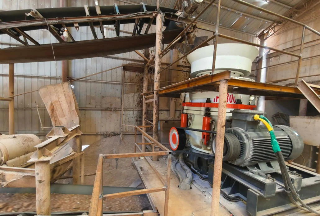
The HP300 is designed around a modular philosophy, yet it presents significant challenges in terms of spatial planning. With a main body height of approximately 3.2 meters and a maximum width of 2.8 meters (inclusive of the hydraulic system), the footprint is substantial. However, the true engineering weight lies in the rotating assembly. Weighing in at roughly 18 tons, the dynamic mass of the internal components generates immense gyroscopic forces during operation. This necessitates a rigorous approach to foundation design and anchoring. The machine is not simply placed on the ground; it must be integrated into a reinforced concrete ecosystem capable of dampening the high-frequency vibrations generated by its eccentric drive.

Foundation Dynamics And Installation Geometry
The interface between the crusher and the earth is critical. The HP300 utilizes a hexagonal distribution pattern for its base mounting holes, featuring a diagonal distance of 2.1 meters. This geometry is engineered to distribute the vertical and horizontal loads evenly across the support structure. When designing the foundation, one cannot simply match the footprint of the machine. To prevent edge-loading and ensure stability under peak crushing forces, the concrete bearing surface must extend at least 0.5 meters beyond the equipment’s base edge on all sides.
This extra margin serves a dual purpose: it provides the necessary mass to counteract the vibrational energy of the 18-ton rotating assembly, and it offers a secure platform for the isolation mounts. Neglecting this spatial requirement can lead to “foundation walking,” where the machine slowly migrates or loosens its anchor bolts due to resonance. Furthermore, the top lifting ring spacing dictates the spreader bar configuration required for safe rigging. During installation, precise alignment is non-negotiable; even a millimeter of deviation can introduce stress concentrations that compromise the lifespan of the frame.
Kinematics: The Physics Of The Swing Stroke
While dimensions define the space the machine occupies, kinematics define what the machine *does* within that space. The heart of the HP300’s performance lies in its optimized swing stroke and eccentric speed. Unlike smaller crushers that rely on rapid, short impacts, the HP300 utilizes a specific stroke amplitude to facilitate deep-cavity crushing and effective inter-particle comminution (layer crushing). This parameter represents the amplitude of the mantle’s movement against the concave.
This stroke is synchronized with a rotational speed range typically between 500-750 rpm (depending on the specific cavity configuration). This wide operating window allows operators to fine-tune the balance between reduction ratio and capacity. At the lower end of the spectrum, the machine maximizes torque for breaking large, hard feed, while the higher end optimizes the shaping of the final product. However, manipulating these variables requires a deep understanding of the drive train. Increasing the speed to improve particle shape will invariably increase the wear rate on the liners. Therefore, the selection of the correct cone crusher part—specifically the liner profile—is crucial to matching the kinematic settings to the ore characteristics.

Hydraulic Versatility And Feed Specifications
The versatility of the HP300 is most evident in its hydraulic adjustment capabilities. The system allows for a continuous, stepless adjustment of the discharge opening (CSS) within a range of 25-70mm (depending on the liner profile selected). This broad range transforms the machine from a secondary crusher into a tertiary unit with simple hydraulic commands. By adjusting the position of the main shaft via the hydraulic pistons, the operator can instantly alter the product gradation without stopping the feed.
This flexibility supports a massive variance in throughput, ranging from 200 to 500 tons per hour. However, to achieve the upper limits of this capacity, the feed geometry must be respected. The feed inlet measures approximately 330mm × 490mm, designed to accept a maximum feed size of roughly 300mm. It is vital to note that “maximum feed size” is not an invitation to push the limit constantly. Feeding material that approaches the limit requires a perfectly choke-fed chamber to prevent bridging. If the feed is inconsistent, the crusher will struggle to utilize its full hydraulic power, leading to fluctuations in the power draw and potential overload trips.
| Specification Category | Technical Parameter | Operational Implication |
|---|---|---|
| Physical Dimensions | Height: ~3.2m | Width: ~2.8m | Requires plant layout with sufficient vertical clearance for liner changes and maintenance access. |
| Kinematics | Speed: 500-750 rpm | Variable speed allows optimization for shape vs. tonnage; requires precise liner matching. |
| Capacity & Output | CSS: 25-70mm | TPH: 200-500 | Wide CSS range enables versatile application (secondary to tertiary); high TPH requires consistent feed. |
Spatial Requirements For Maintenance And Safety
A common oversight in plant design is failing to account for the “human factor”—the space required for technicians to actually work on the machine. The HP300 demands generous clearances. A minimum maintenance passage of 1.8 meters is required around the perimeter of the equipment. This is not merely for walking; it is the working radius needed to remove side covers, access the hydraulic cylinders, and maneuver replacement components.
Furthermore, the vertical space above the crusher is just as critical as the floor space. A lifting height of no less than 5 meters is mandatory above the crusher. This clearance accommodates the crane or hoist required to lift the heavy rotating assembly or the feed hopper. Without this vertical volume, changing the mantle or concave becomes a logistical nightmare involving complex rigging maneuvers that increase safety risks and downtime. Additionally, the lubrication and hydraulic units require a dedicated operational zone of 1.2 meters × 1.5 meters. This area must remain unobstructed to allow for filter changes, oil sampling, and pressure monitoring. Crowding this space with ancillary piping or cabling is a violation of good engineering practice and creates a hazardous environment.

Optimizing Lifecycle Through Intelligent Part Selection
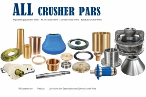
The longevity of the HP300 is heavily dependent on the quality of its consumables. Because the machine operates with such high kinetic energy, the cone crusher wear parts are subjected to extreme cyclical loading. The choice of manganese steel grade—whether Mn18, Mn22, or specialized alloys with titanium carbide inserts—must align with the abrasiveness of the feed material.
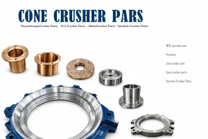
Using inferior liners can lead to rapid degradation of the head and seat, effectively destroying the precision geometry we discussed earlier. Moreover, when sourcing cone crusher spare parts, one must consider the tolerances of the bushings and seals. The hydraulic system operates at high pressures to maintain the CSS; if the sealing surfaces on a replacement part are not machined to exact specifications, internal leakage will occur, causing the crusher to lose clamping force and compromising the product size. Therefore, maintenance is not just about swapping metal; it is about preserving the calibrated state of the machine.
Lifting And Rigging Logistics
Finally, let us address the logistics of handling this machinery. The recommendation to configure 10-ton class lifting equipment is based on the weight of the heaviest sub-assemblies, such as the adjustment ring or the main shaft assembly. While the total machine weight is higher, the modular design allows for piece-by-piece dismantling. However, the lifting points are designed for specific load vectors. Improper rigging—using chains that are too short or shackles that are undersized—can deform the lifting lugs or crack the casting. Always verify the Working Load Limit (WLL) of your rigging gear against the certified weights of the HP300 components before initiating any lift.
In summary, the HP300 is a masterpiece of mechanical engineering that demands respect for its physical and dynamic limits. By adhering to the strict dimensional guidelines for installation, respecting the kinematic parameters during operation, and maintaining rigorous standards for spare parts, operators can ensure that this machine delivers its promised capacity for years to come.