Ten Operating Protocols That Determine Whether Your Cone Crusher Parts Last 3,000 Hours or 800
A mantle manufactured from Mn18Cr2 austenitic manganese steel — hardness ranging between 180 and 220 HBW in its work-hardened state — can fail in under 800 operating hours if the feed distribution is wrong. I have seen this happen on a 4,000 t/d copper concentrator where a misaligned chute was directing ore off-center onto the crushing head. The resulting uneven loading caused accelerated spalling on one side of the concave ring and a catastrophic shear event at the 6 o’clock position. The plant lost 11 days of production. Every crusher part supplier I have worked with in the past two decades will tell you the same thing: material grade accounts for roughly 40% of wear life; operating discipline accounts for the rest.
This article distills the ten most critical operating and maintenance protocols for cone crusher parts, grounded in engineering parameters drawn from real field work across iron ore, copper, and aggregate operations. Whether you source crusher wear parts from an OEM or from experienced crusher spare parts manufacturers in the aftermarket, these protocols apply without exception.
Protocol 1: Feed Must Land on the Distribution Plate, Not Directly Into the Crushing Chamber
This is the rule most frequently violated, and it carries the highest consequence. Ore fed directly into the crushing chamber without passing through the distribution plate creates a non-uniform loading profile across the mantle surface. The result is selective wear — a phenomenon where localized contact stress exceeds 180 MPa on one arc of the concave while adjacent areas remain underloaded. Over a 1,000-hour service period, this produces measurable dimensional asymmetry in the crusher wear parts and accelerates the failure mode known as mushrooming, where the mantle lip deforms upward under repeated eccentric impact.
The correct feed condition is one where ore disperses radially and uniformly across the full 360° of the crushing chamber, with the maximum feed level not exceeding the upper rim of the concave. Any crusher part supplier providing a quality mantle to ASTM A128 Grade B-3 specification will caveat its wear life guarantee against improper feed distribution.
Protocol 2: Maximum Feed Size Must Not Exceed 85% of the Feed Opening
This threshold is not arbitrary. When oversized material enters the chamber, it transmits shock loads that bypass the designed crushing force path and act directly on the eccentric assembly and main shaft. At a 500 kW machine running at 285 RPM, an oversize event lasting just 4 seconds can generate torsional stress spikes exceeding the fatigue limit of a standard 42CrMo4 main shaft. Beyond shaft risk, oversize feed degrades throughput — a 10% exceedance of the 85% rule typically reduces capacity by 15–22%, according to measurements I have taken on HP300-class machines in granite quarries.
Experienced crusher spare parts manufacturers design their mantles with defined choke zones, and exceeding the feed size specification directly undermines that geometry. Install a grizzly or pre-screen with apertures set to no more than 85% of the CSS before material reaches the crusher.
Protocol 3: Never Start the Crusher Under Load
A loaded start subjects the eccentric bearing — typically a C93800 leaded bronze bushing with a radial clearance of 0.25–0.40 mm — to instantaneous boundary lubrication failure. At ambient temperatures below 10°C, oil viscosity in an ISO VG 220 gear oil can rise sufficiently to delay the formation of a hydrodynamic film by 3–5 seconds after startup. Starting under load during these conditions causes metal-to-metal contact across a bearing surface area exceeding 600 cm², producing galling damage that no crusher part supplier can reverse without a full bushing replacement.
Interlock the feed system electrically so that ore flow cannot begin until the main motor has reached full operating speed and the lubrication system confirms oil pressure above 0.12 MPa at the main bearing gallery.
Protocol 4: Shut Down in the Correct Sequence
Stop the feeder first. Allow all material already inside the crushing chamber to be fully discharged before cutting power to the main drive. Skipping this step leaves compacted ore against the mantle surface. On restart, if the locking system was not engaged, the weight of trapped ore combined with the eccentric throw — typically 22–38 mm on a medium-cone machine — creates a bending moment that can crack the lower frame assembly. This failure mode is entirely preventable and represents one of the most wasteful sources of crusher parts expenditure in the industry.
Protocol 5: Monitor Hydraulic Locking System Pressure Continuously
The hydraulic locking cylinder on a modern cone crusher maintains clamp pressure on the adjustment ring at between 12 and 18 MPa during normal operation. A pressure drop of more than 2 MPa below the setpoint, sustained for longer than 30 seconds, indicates either a seal failure in the locking cylinder or a volume loss in the accumulator circuit. Ignoring this symptom allows the adjustment ring to rotate under load — a condition that strips the thread form on both the ring and the main frame within hours. The replacement cost of a main frame thread repair on a 660-class machine has reached USD 180,000 in recent projects I have assessed. Monitor the hydraulic station gauges at every operator walkdown, minimum every two hours.
Protocol 6: Replace and Torque Concave and Mantle Correctly
The concave (bowl liner) is secured to the adjustment ring with U-bolt assemblies, and the gap between the liner and its seat is filled with a zinc alloy (typically ZA-12, melting point 386°C) to ensure full-contact load distribution. After installation of new crusher wear parts, the zinc alloy contracts slightly as it cools, reducing the clamp load on the U-bolts. This is not a defect — it is a predictable material behavior. The mandatory protocol is to re-torque all U-bolts to the specified value (typically 450–680 Nm depending on bolt diameter) after the first 6 to 8 hours of operation under load.
Pro-Tip from the Field: I mark each U-bolt head with a paint pen after final torque. On the next 6-hour check, any paint crack or rotation of the mark is immediately visible. This takes 10 minutes and has saved us from three bowl liner walkout events in the past five years alone.
The mantle is fixed to the crushing head using a head nut, with ZA-12 cast between the mantle and the head body to a minimum fill verified by probing all pour holes before the alloy solidifies. Surface roughness at the mantle-to-head contact interface should be Ra ≤ 1.6 μm for proper alloy adhesion. The same 6–8 hour re-check protocol applies.
Protocol 7: Compensate for Circular Plate Wear with Shim Adjustment
The bevel gear set — usually cut from case-hardened 20CrMnTi steel to a 58–62 HRC surface hardness — depends on a precise backlash of 0.25–0.45 mm to maintain a full elastohydrodynamic oil film at the tooth contact zone. As the circular plate beneath the pinion shaft bearing housing wears, the pinion drops and backlash increases. Every 0.1 mm of plate wear that goes uncompensated reduces the oil film thickness and accelerates pitting on the gear tooth flanks. Add shim stock equal in thickness to the measured plate wear, verified with a dial indicator against the gear housing datum. Ignoring this adjustment is one of the top three reasons crusher parts fail prematurely in high-tonnage operations.
Protocol 8: Inspect Bowl Bearing Assembly and Sealing System to Tolerance
The spherical bowl bearing — bronze, typically C83600 or equivalent, with a minimum hardness of 60 HBW — must maintain an annular clearance of 0.35–0.50 mm between the inner bronze surface and the crushing head ball. If this clearance falls below 0.30 mm due to thermal expansion during high-ambient-temperature operation, the oil film collapses and catastrophic adhesive wear begins within minutes. If it exceeds 0.55 mm, impact loads generate fretting corrosion on the bronze surface.
The bowl bearing is locked against rotation by Babbitt alloy (white metal, Pb-Sn-Sb composition) poured around locking pins. If the bearing frame develops any measurable rotational movement relative to the main frame during operation, shut down immediately and inspect. A 0.5 mm rotational slip detected early costs one shift. Detected after 200 hours, it costs a frame.
Field Case Snippet: On a secondary crushing circuit in a lead-zinc concentrator, we identified a bowl bearing frame with 0.8 mm of fretting wear on its locating key after an oil sample returned an iron particle count of 420 ppm — roughly four times the action threshold. The bearing had been in service for only 1,100 hours. Root cause was a lubrication circuit check valve that was allowing reverse flow and draining the bearing gallery during coast-down. We replaced the valve for USD 180, the bearing frame for USD 12,400, and avoided what would have been a main frame crack costing an estimated USD 90,000. Oil analysis is not optional maintenance — it is early warning infrastructure.
Protocol 9: Set Spring Pressure Correctly and Investigate Bounce Immediately
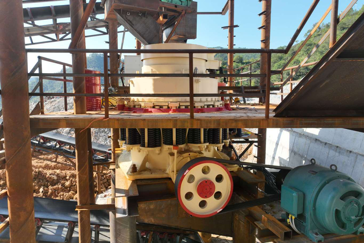
The tramp release spring assembly is the crusher’s last line of defense against uncrushable material. Springs are pre-compressed to a load that matches the designed crushing force — on a medium secondary cone this is typically 850–1,100 kN of clamp force across the ring. Under normal operation, the springs do not move. They lift the support ring only when an uncrushable object, such as a steel drill bit or a tramp iron fragment, enters the chamber and creates a force spike beyond the set load.
If the upper assembly is bouncing during normal operation with normal feed, the cause is one of three conditions: feed rate exceeds the choke capacity of the chamber; the CSS is set below the minimum recommended for the feed gradation; or the feed contains excessive fines and moisture, reducing the effective void space between particles and creating hydraulic locking. Do not respond to this symptom by increasing spring pre-compression. Doing so raises the effective crushing force, increases bearing load beyond design limits, and converts a reversible operating condition into an irreversible mechanical failure. Diagnose the root cause, then correct the operating condition.
Protocol 10: Cylindrical and Tapered Sleeve Fit Tolerances Must Be Verified at Every Replacement
The cylindrical eccentric bushing and the tapered (conical) sleeve are interference-fit components. The cylindrical bushing is a Grade 3 transitional fit — meaning the actual interference can range from slight clearance to slight interference depending on measured bore and shaft diameters. After extended operation and multiple disassembly cycles, the bore in the main frame casting grows due to fretting and thermal cycling. A bushing installed to nominal dimension into an oversize bore will have insufficient interference and will rotate in service. Rotation of a 180 kg bronze bushing at 285 RPM generates enough frictional heat to melt the ZA-12 retaining alloy in the keyway within 40 minutes, followed by catastrophic bushing migration.
Always measure the actual bore before ordering replacement crusher wear parts. Responsible crusher spare parts manufacturers can machine replacement bushings to actual bore dimensions rather than nominal drawing dimensions. The tolerance stack on a properly fitted cylindrical bushing should target 0.02–0.05 mm interference at operating temperature, accounting for the differential thermal expansion between the bronze bushing and the cast steel frame.
Total Cost of Ownership: OEM vs. Quality Aftermarket Crusher Parts
| Parameter | Low-Cost Aftermarket | Quality Aftermarket / OEM-Standard |
|---|---|---|
| Mantle material grade | Mn14Cr2 or unspecified | Mn18Cr2, ASTM A128 Grade B-4 |
| Average wear life (t/piece) | 600,000 – 800,000 t | 1,100,000 – 1,400,000 t |
| Unit price (USD, HP400-class) | USD 4,200 | USD 6,800 |
| Cost per million tonnes (USD) | 5,600 – 7,000 | 4,850 – 6,180 |
| Average change-out downtime | 14 hours (more frequent) | 14 hours (less frequent) |
| Secondary damage risk | High (dimensional drift) | Low (controlled geometry) |
The data above is drawn from production records across six operating sites. A crusher part supplier offering significantly lower prices than the OEM-standard market should be asked to provide chemistry certifications (C, Mn, Cr, Si percentages), Charpy impact test results at −20°C, and dimensional inspection reports with surface finish measurements. Without these documents, the price comparison is meaningless — the variables are not equivalent.
Preventive Maintenance Based on Oil Analysis
Scheduled oil sampling from the lubrication system every 250 operating hours provides early detection of component degradation before it becomes visible or audible. Key markers and their action thresholds for a cone crusher lubrication circuit are as follows:
- Iron (Fe): Action level above 100 ppm; indicates bushing or gear wear. Above 250 ppm, shut down for inspection.
- Copper (Cu): Action level above 50 ppm; indicates bronze bushing wear or heat-induced alloy transfer.
- Lead (Pb): Action level above 30 ppm; indicates Babbitt bearing surface deterioration.
- Zinc (Zn): Elevated levels may indicate ZA-12 alloy dissolution from liner seats — a sign of loose liner fit.
- Particle count (ISO 4406): Target cleanliness code 18/16/13 or better. Above 20/18/15, change the filter and resample at 50 hours.
- Viscosity at 40°C: Should remain within ±10% of ISO VG 220 specification. Viscosity drop indicates fuel or solvent ingress; viscosity rise indicates oxidation or contamination.
No crusher part supplier or crusher spare parts manufacturer can extend wear life beyond what the lubrication system delivers to the friction interfaces. Oil analysis is the single highest-return maintenance investment available to a crushing plant operator.
The ten protocols described in this article are not theoretical — they are the direct product of failure investigations, component measurement campaigns, and production cost analyses conducted across operating mines and quarries. Crusher parts fail for compounding reasons: a feed distribution problem that stresses the mantle asymmetrically, combined with a bowl bearing clearance that has drifted 0.1 mm beyond its upper limit, combined with an oil sample that was never taken, produces a failure that appears sudden but was months in the making.
Whether you are working with an established crusher part supplier or evaluating crusher spare parts manufacturers for the first time, hold every component to the same engineering standard: documented material chemistry, dimensional inspection to ±0.05 mm tolerance, surface finish verification, and a traceable heat number on every casting. Apply the operating protocols above, and a quality cone crusher part will deliver the service life it was designed to provide.