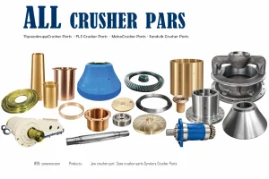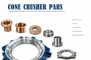
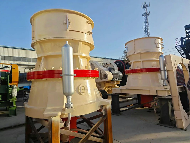
Installation of a primary or secondary crusher begins long before the machine arrives on site. The structural integrity of the concrete foundation dictates the harmonic vibration levels and the ultimate fatigue life of the mainframe. For a standard 200-300 kW cone or jaw crusher, the foundation must utilize C30 or higher grade concrete, ensuring a minimum compressive strength of 30 MPa after a 28-day curing cycle. A common failure in rapid-build projects is mounting equipment on “green” concrete that has not reached 75% of its design strength, leading to microscopic subsidence that throws the drive train out of alignment.The leveling plates must be set with an accuracy of 0.1 mm per meter. We utilize laser leveling tools to verify that the support surfaces are perfectly co-planar. Any deviation here creates a “soft foot” condition, where the crusher frame twists under the tension of the anchor bolts. This mechanical stress migrates from the frame to the internal bushings and eventually affects how the crusher wear parts seat within the chamber. If the frame is distorted by even 0.5 mm, the eccentric motion will be uneven, causing localized heat spikes and premature component failure.Anchor bolts should be pre-set using high-strength non-shrink grout. We typically specify M36 or larger bolts for heavy-duty applications, tensioned to 70% of their yield strength using a hydraulic torque wrench. The goal is to create a monolithic bond between the steel frame and the concrete mass, effectively turning the foundation into a giant dampening block for the kinetic energy generated during the crushing cycle.
Mechanical Assembly and Drive Train Alignment
Once the frame is secured, the focus shifts to the drive assembly. Whether using a direct-drive coupling or a V-belt arrangement, the alignment between the motor shaft and the crusher pinion shaft is critical. For V-belt drives, the grooves must be aligned within a tolerance of 0.5 degrees. Excessive angular misalignment causes the belts to “roll” in the grooves, generating frictional heat that can reach 90 °C, rapidly degrading the rubber compound and increasing the radial load on the motor bearings.The tensioning of the belts must follow the manufacturer’s deflection force table. For a 5V or 8V belt profile, we measure the force required to deflect the belt mid-span. Under-tensioning leads to slippage during “tramp iron” events, while over-tensioning causes the pinion shaft bearings to run hot. During this phase, it is also essential to organize the crusher spare parts inventory, ensuring that a set of matched belts and spare pulleys are labeled and stored in a climate-controlled environment to prevent ozone cracking.
Installing Internal Components and Crusher Wear Parts
The installation of the mantle and concave (or jaw plates) is the most critical task for ensuring immediate production quality. Before seating the mantle on the head ball, all mating surfaces must be cleaned of protective shipping grease using a high-flashpoint solvent. Any grit left between the mantle and the head will create a high spot, leading to “liner rattling” which can eventually crack the head casting. Every high-quality crusher wear parts set requires a specific backing compound—usually a two-part epoxy resin—to fill the void between the liner and the support structure.The backing compound must be poured at an ambient temperature between 15 °C and 25 °C to ensure proper flow and curing. If the compound is too cold, it will not fill the lower voids; if too hot, it may flash-set, creating air pockets. We allow a minimum of 6 to 12 hours for the compound to reach full hardness before introducing any mechanical load. While the liners are curing, the technician should verify the closed-side setting (CSS) using lead slugs. This baseline measurement ensures that the crusher wear parts are positioned to produce the required product gradation from the first ton of feed.
| Installation Phase | Technical Specification | Tolerance / Value | Associated Resource |
|---|---|---|---|
| Foundation Curing | Compressive Strength | > 30 MPa | Civil Works |
| Base Plate Leveling | Planarity | 0.1 mm / 1000 mm | Precision Machining |
| Belt Alignment | Angular Deviation | < 0.5 Degrees | Mechanical Drive |
| Liner Backing | Hardness (Shore D) | 80 – 90 | Crusher wear parts |
| Oil Filtration | ISO Cleanliness Code | 16/14/11 | Crusher spare parts |
Lubrication and Hydraulic System Commissioning
Before the first rotation of the eccentric, the lubrication system must be flushed. We use a dedicated flushing pump and a 20-micron return filter to circulate oil for at least 4 hours. This process removes any construction debris, metal shavings, or dust that entered the piping during installation. The oil must be pre-heated to 40 °C to lower its viscosity, allowing it to penetrate the narrow oil galleries in the internal bushings. A clean lubrication circuit is the best insurance for the various crusher spare parts that reside within the machine’s core.The hydraulic system, responsible for tramp release and setting adjustment, requires a separate pressure test. We pump the system to 110% of its maximum operating pressure (typically around 20-25 MPa) and hold it for 30 minutes. If the pressure drops more than 0.5 MPa, it indicates a leaking seal or a loose fitting. Ensuring hydraulic integrity prevents “drifting” of the adjustment ring, which would otherwise lead to inconsistent product size and uneven loading on the crusher wear parts.
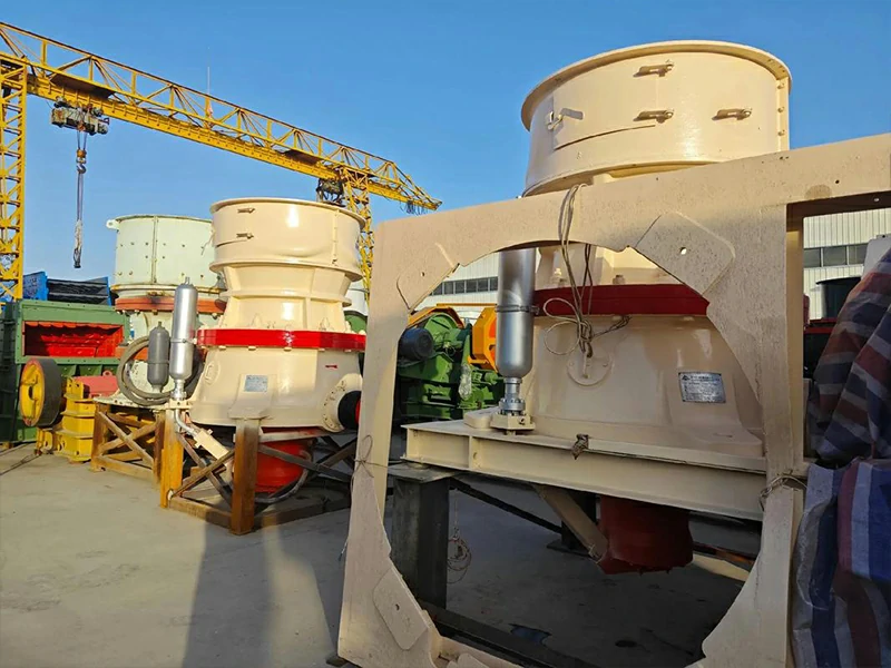
Dry and Wet Run Procedures
Commissioning follows a 2-4-8 hour protocol. The initial 2-hour “dry run” is performed without feed. During this time, we monitor the “no-load” current of the motor and the vibration velocity at the bearing housings. Vibration should not exceed 4.5 mm/s RMS. We also use a thermal imaging camera to check the temperature of the countershaft box and the hydraulic tank. If the lubrication oil temperature stabilizes below 50 °C, we proceed to the 4-hour partial load test.The wet run introduces material at 50% of the rated capacity. This is the first time the crusher wear parts experience real-world compressive stress. We observe the “crushing noise”—it should be a consistent, rhythmic growl. Any high-pitched metallic shrieking indicates that a liner is loose or that the eccentric bushing is experiencing localized friction. Finally, an 8-hour full-load test confirms that the cooling system can handle the thermal load generated by high-tonnage production. During this entire process, having a comprehensive kit of crusher spare parts on hand—including temperature sensors, pressure switches, and spare filters—is vital for addressing minor teething issues without delaying the project timeline.
Strategic Spare Parts Management for New Installations
The final step of a successful installation is the establishment of a localized inventory. A new machine is most vulnerable during its first 500 hours of operation. Critical crusher spare parts such as eccentric bushings, thrust washers, and a complete seal kit should be stored on-site in an organized rack system. We recommend applying a light coat of rust-preventative oil to all machined steel surfaces before storage.Furthermore, the lifecycle of the crusher wear parts must be tracked from day one. By recording the tonnage processed against the wear measured in millimeters, the site manager can predict exactly when the next liner change is required. This data-driven approach prevents the common mistake of running liners until they are paper-thin, which risks damaging the permanent internal components of the crusher. A well-executed installation, supported by a robust parts strategy, ensures that the equipment delivers its design performance for decades, not just months.In summary, installing a crusher is an exercise in managing tolerances and thermal energy. From the C30 concrete of the foundation to the ISO 16/14/11 cleanliness of the lubrication oil, every detail contributes to the mechanical efficiency of the system. When the foundation is level, the drive train is aligned, and the crusher wear parts are correctly backed and seated, the machine will operate within its design parameters, providing the lowest cost-per-ton and the highest return on investment for the operator.