

Bronze Thrust Plate main shaft step 57-6600-001
Replacement Main Shaft Step Thrust Plate Compatible with Symons 4.25 Ft & 5.5 Ft — Premium Cone Crusher Parts
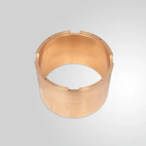
Main Shaft Step — Bronze Thrust Plate for Symons Cone Crushers
The main shaft step is the primary axial load-bearing component in a cone crusher drive assembly. Positioned at the base of the main shaft within the bottom shell, it absorbs the full downward thrust force generated during crushing and transmits that load to the bottom shell frame through a precisely machined seating surface. In a 5.5 ft Symons-type cone crusher operating at rated capacity, this thrust load can exceed 400 kN under peak crushing conditions. Selecting a correctly specified main shaft step is not a secondary procurement decision — it is a prerequisite for protecting the main shaft, eccentric assembly, and bottom shell bore from accelerated wear and thermal distress.
Material Specification and Oil Groove Design
This main shaft step is cast from high-leaded tin bronze conforming to ASTM B22 Alloy C93700, with a nominal composition of 80 percent copper, 10 percent tin, and 10 percent lead. The dispersed lead phase in the microstructure acts as a boundary-phase lubricant at the bearing interface during startup, before hydrodynamic oil pressure has fully developed across the contact surface. Brinell hardness in the as-cast condition runs HB 55 to HB 70. Compressive yield strength is approximately 90 MPa — sufficient to resist plastic deformation under sustained axial thrust without generating metallic transfer to the hardened steel shaft seat above it.
The upper face of the step is machined with a radial petal-pattern oil groove array. These grooves serve two functions simultaneously. They distribute pressurized lubricating oil from the central supply port across the full bearing surface during normal operation, maintaining a continuous hydrodynamic film between the rotating shaft and the stationary plate. They also act as debris escape channels, allowing fine metallic wear particles generated during boundary contact at startup to migrate away from the load zone rather than building up and scoring the bearing face. Oil groove depth is held at 1.5 to 2.0 mm, with groove width of 4 to 6 mm, machined to a surface roughness of Ra 3.2 to 6.3 μm. The flat load-bearing lands between grooves are finish-machined to Ra 0.8 to 1.6 μm to support proper film formation under full operating load.
Dimensional Compliance
The outer diameter, inner bore (where applicable), overall thickness, and seating surface flatness are machined to the OEM-specified drawing tolerance for the target crusher model. Seating surface flatness on the underside contact face is held within 0.05 mm across the full diameter to ensure even load distribution against the bottom shell seat. Thickness tolerance across the step body is maintained at ±0.10 mm. All critical dimensions are verified on a coordinate measuring machine prior to dispatch, and a dimensional inspection report is available upon request.
Compatibility Reference
| Crusher Model | Step Outer Diameter (mm) | Thickness (mm) | Reference Part Number |
|---|---|---|---|
| Symons 4.25 Ft Standard / Short Head | 260 – 280 | 38 – 42 | 57-6600-001 |
| Symons 5.5 Ft Standard / Short Head | 320 – 340 | 45 – 50 | 1048228 |
| Symons 7 Ft Standard / Short Head | 390 – 420 | 55 – 60 | 1048229 |
| Sandvik CH660 / CH870 | 340 – 360 | 48 – 52 | 452.0531-001 |
Installation and Usage Precautions
- Confirm shaft seat condition before installation. Inspect the bottom shell seat and the lower end of the main shaft for fretting marks, scoring, or out-of-round wear. A worn shaft seat with more than 0.15 mm radial deviation will generate uneven contact stress on the new step face and initiate surface fatigue within the first operating cycle. Restore shaft and seat geometry to drawing specification before fitting a replacement component.
- Verify oil supply flow rate before startup. The lubrication system must deliver clean, filtered oil to the step at the crusher-specific specified flow rate — typically 15 to 25 litres per minute for 5.5 ft class cone crusher parts — before the main drive motor is energised. Starting the machine dry, even briefly, generates boundary contact temperatures that can transfer bronze material to the shaft face and permanently score both surfaces.
- Use only OEM-specified lubricant grade. Most Symons and similar crusher manufacturers specify ISO VG 220 or ISO VG 320 gear oil with extreme-pressure additive package for the bottom shell lubrication circuit. Substituting a non-EP oil or a lighter viscosity grade reduces film thickness at operating temperature and accelerates step wear.
- Do not mix old and new step components. When replacing the main shaft step as part of planned cone crusher parts maintenance, inspect the mating shaft pad and bottom shell socket simultaneously. Fitting a new step against a worn counterpart creates a geometric mismatch that concentrates load on a small contact area and defeats the design intent of the oil groove distribution pattern.
- Torque seating cap screws to specification. Where the step is retained by fasteners rather than a press fit, apply the manufacturer-specified torque value in a cross-pattern sequence. Under-torqued fasteners allow the step to micro-rotate during operation, fretting the seating face and generating metallic debris that contaminates the lubrication circuit of the full eccentric drive assembly.
- Monitor oil return temperature as a wear indicator. A rising oil return temperature — more than 10 °C above the established steady-state baseline at constant throughput — is the earliest reliable field indicator of deteriorating step condition. Do not wait for audible symptoms before scheduling inspection, as acoustic changes in cone crusher parts assemblies typically appear only after significant surface damage has already occurred.
| Weight | 124 kg |
|---|
All manufacturer names, part numbers, model numbers, and descriptions are used for reference and identification purposes only, they are owned by the respective machine manufacturer, including but not limited to FLSmidth®, Metso®, thyssenkrupp®, and Sandvik®. All parts supplied are manufactured and warranted by yonsmen and are not manufactured by or purchased from the Original Equipment Manufacturer. yonsmen has no association with the OEM and does not intend to give this impression.
Reviews
There are no reviews yet.