Preventing Eccentric Bushing Scoring in Primary Crushing
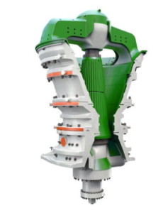
Boundary lubrication conditions in the eccentric assembly of a Flsmidth TSUV Gyratory Crusher KB 63-13ou Pro can score bronze bushing surfaces and generate metallic contamination within seconds of an oil flow interruption. Unplanned downtime in primary crushing circuits is frequently traced back to deferred maintenance on systems that cost very little to manage correctly. The longevity and throughput reliability of this large-format gyratory crusher depend entirely on the rigor of preventive maintenance programs rather than reactive repairs.
Lubrication System Management and Oil Quality
The KB 63-130 Pro operates two completely separate lubrication circuits. The main lube circuit delivers pressurized, filtered, and temperature-controlled circulating oil to the eccentric bushings, mainshaft bushing, and bevel gear drive system. Continuous operation of this forced-feed pressure lubrication system is non-negotiable during crusher operation. The spider assembly grease circuit operates independently via a timed automatic grease-injection system, delivering metered shots of high-consistency grease to the spider bushing and grease seals at the machine crown. Cross-contamination between these two circuits must be structurally prevented in both plumbing layout and procedural control.
Four parameters determine whether the main circuit oil is protecting the machine or destroying it. The temperature differential across the cooler must not exceed 8°C under steady-state operating conditions. A creeping delta-T is often the first indicator of reduced oil flow caused by a partially blocked strainer, a failing pump, or restricted passages in the eccentric assembly. Oil analysis must be conducted every three months without exception. Laboratory reports should cover an ISO cleanliness code target of 16/14/11 for this class of equipment, water content below 0.1% by volume, and spectrometric metals analysis. Rising copper or tin levels indicate eccentric bushing wear, while elevated iron points toward gear or housing erosion. The sump level must never fall below the low-level mark, as this reduces thermal mass, increases oil temperature, and risks cavitation in the supply pump. When the high differential pressure alarm triggers, the filter element must be changed immediately and an oil sample submitted before restarting.
Hydraulic System Purity and Pressure Tolerance
The hydraulic system supports the full weight of the mainshaft and mantle assembly through the hydraulic cylinder and enables closed-side setting adjustment without machine disassembly. It also provides automatic tramp-iron protection by releasing cylinder pressure when an uncrushable object enters the cavity. Maintaining this system requires strict adherence to fluid specifications. The system uses ISO VG 46 or VG 68 mineral hydraulic oil depending on ambient site temperatures. This oil must be stored, transferred, and contained in dedicated equipment and never shared with the main lube circuit.
Working pressure should be maintained within ±5% of the design set point. Significant pressure drift indicates a control valve issue, seal degradation, or cylinder blow-by and must be investigated the same shift it is detected. Hydraulic oil must be replaced annually on a calendar basis or immediately if oil analysis shows contamination, degraded viscosity index, or water ingress above 0.05%. A healthy hydraulic cylinder in this application should produce no more than 1 ml of external leakage per 100 strokes of piston travel. If leakage exceeds this threshold, the wiper ring and piston seal assembly should be inspected at the next planned shutdown. Closed-side setting adjustments must always be performed with the feed belt stopped and the crushing cavity empty to prevent pressure transients that can damage the position transducer.
Condition-Based Wear Part Replacement Strategy
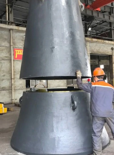
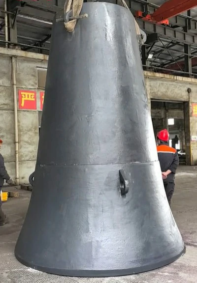
Mantle and concave wear are the most significant cost drivers in any gyratory crusher operation. Waiting for visual confirmation of worn-through hardware means allowing production loss, geometrical deviation, and potential damage to the backing material or mantle core. Replacement triggers must be based on measured condition rather than fixed calendar intervals because ore hardness, feed size distribution, and feed moisture all affect actual wear rates significantly.
| Wear Part | Replacement Trigger | Measurement Method | Typical Interval |
|---|---|---|---|
| Upper Mantle | Thinnest point ≥ 50% wall loss | Laser gauge / Ultrasonic | 3–6 months |
| Lower Mantle | Thinnest point ≥ 55% wall loss | Laser gauge / Ultrasonic | 4–8 months |
| Concaves | CSS out of range with adjustment travel exhausted | CSS measurement | 4–12 months |
| Spider Bushing | Radial clearance > 0.15 mm | Bore gauge (multi-section) | 1–2 years |
| Eccentric Bushings | Radial clearance > 0.25 mm | Bore gauge | 1.5–3 years |
| Countershaft Bearings | Abnormal vibration or temperature | Vibration analysis | 3–5 years |
The middle concave consistently wears faster than the upper and lower sections because it occupies the primary compression zone of the crushing cavity. Budget for more frequent middle concave changes and track its wear rate separately. When replacing mantles, never reuse backing material. Remove all residual epoxy backing completely, inspect the mantle core surface for erosion or cracking, and re-pour fresh backing compound to the manufacturer-specified mix ratio and cure time. Premature mantle failure in the field is disproportionately caused by poor backing practice rather than inferior wear steel. Bushing measurements must be taken at a minimum of three cross-sections because eccentric loading causes tapered wear that a single-point measurement will understate significantly.
Scheduled Shutdown Maintenance Framework
Effective maintenance for a primary crushing machine is a layered program of increasing depth and interval. The following framework is designed for high-utilization primary crushing service exceeding 6,000 hours per year.
- Shift Inspection. Conducted every shift to monitor lube oil level and temperature, hydraulic pressure, instrument readings, audible and vibration checks, and closed-side setting visual estimates.
- Weekly Inspection. Performed every 7 days to confirm spider grease injection volume, conduct visual seal leak checks, perform bolt torque spot-checks, and verify cooling water flow rates.
- Monthly Inspection. Executed every 30 days to measure liner wall thickness, check drive belt tension, and verify instrument calibration.
- Quarterly Inspection. Completed every 90 days to conduct lube oil sampling and analysis, check hydraulic oil level and condition, perform countershaft bearing vibration analysis, and measure eccentric bushing clearance.
- Annual Major Overhaul. Scheduled every 12 months for full machine disassembly, planned wear parts replacement, geometric accuracy surveys including concentricity and perpendicularity, and non-destructive testing of mainshaft, eccentric, and shell critical zones.
The shift-level inspection is the most important intervention in this hierarchy because it catches developing problems before they become failures. A thermal anomaly in the lube oil delta-T, a change in the acoustic signature, or an unexpected closed-side setting drift detected at shift handover can be investigated during the next planned window rather than triggering a breakdown repair. The annual major overhaul should be treated as a planned geometric and structural audit. Use a certified dimensional survey contractor to verify mainshaft concentricity, mantle core geometry, and concave support ring condition. Year-on-year comparison of these records serves as one of the most powerful predictive maintenance tools available to a primary crushing engineer.