Gyratory Crusher Parts Names and Functions
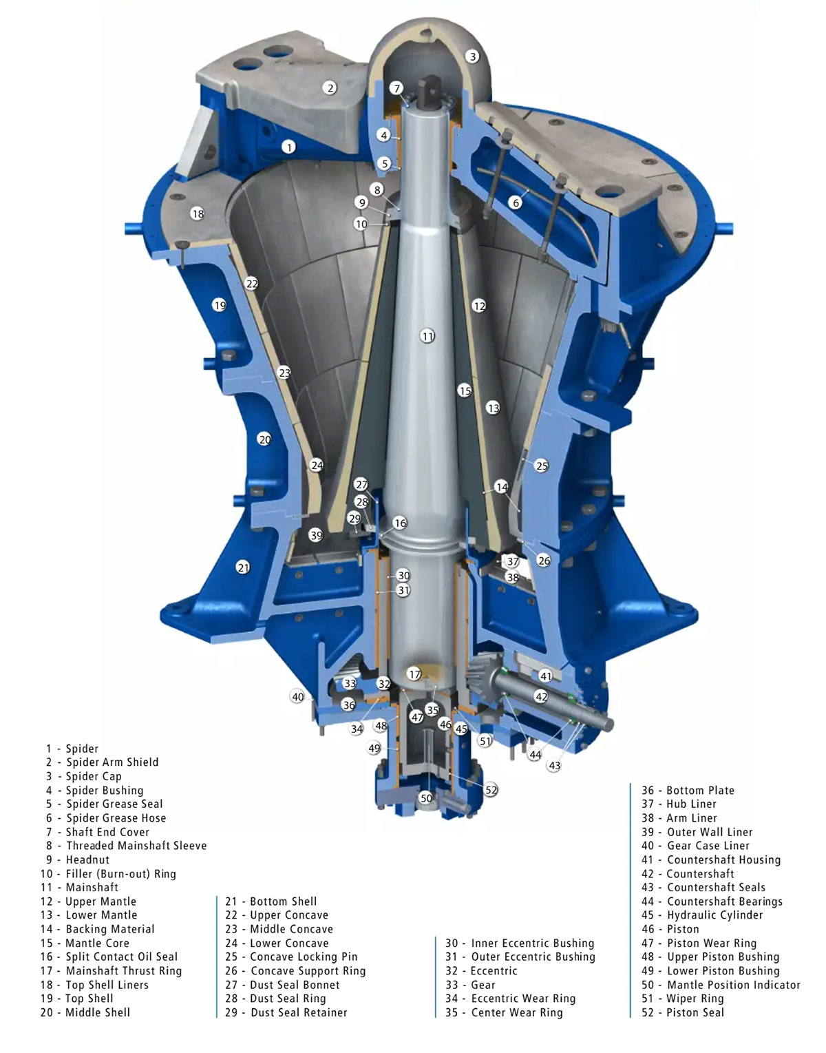
The following list is organized according to the numbers shown in the image. It includes each part name and its main function for equipment identification, spare parts sourcing, maintenance planning and repair reference.
Parts List
| No | Part Name | Function |
| 1 | Spider | Supports the upper end of the mainshaft and helps keep the shaft stable during crushing operation. |
| 2 | Spider Arm Shield | Protects the spider arms from rock impact and abrasive wear. |
| 3 | Spider Cap | Covers the center area of the spider and helps prevent dust and material from entering the bearing area. |
| 4 | Spider Bushing | Supports the upper mainshaft and reduces friction between the shaft and spider assembly. |
| 5 | Spider Grease Seal | Seals the spider lubrication area and helps prevent grease leakage and dust entry. |
| 6 | Spider Grease Hose | Delivers grease to the spider bushing area to maintain proper lubrication. |
| 7 | Shaft End Cover | Covers and protects the shaft end from contamination and external damage. |
| 8 | Threaded Mainshaft Sleeve | Protects the threaded area of the mainshaft and helps secure upper locking components. |
| 9 | Headnut | Locks the mantle assembly in position and helps prevent loosening during crushing. |
| 10 | Filler Burn out Ring | Fills and positions the related gap and can be removed by heating during maintenance. |
| 11 | Mainshaft | Supports the mantle assembly and transfers crushing force through the moving Gyratory structure. |
| 12 | Upper Mantle | Works with the concave liner to crush material in the upper crushing chamber. |
| 13 | Lower Mantle | Works with the lower concave liner to complete the main compression crushing process. |
| 14 | Backing Material | Fills the space behind liners, absorbs impact and improves liner support stability. |
| 15 | Mantle Core | Supports the mantle liners and forms the main body of the moving Gyratory assembly. |
| 16 | Split Contact Oil Seal | Seals the lubrication oil area and helps prevent oil leakage and dust contamination. |
| 17 | Mainshaft Thrust Ring | Supports axial load from the mainshaft and limits unwanted axial movement. |
| 18 | Top Shell Liners | Protect the inner wall of the top shell from material impact and wear. |
| 19 | Top Shell | Forms the upper machine structure and supports the spider and upper liner components. |
| 20 | Middle Shell | Connects the upper and lower shell structures and supports the middle crushing chamber. |
| 21 | Bottom Shell | Acts as the main base structure and supports the drive system and lower machine components. |
| 22 | Upper Concave | Works with the upper mantle to form the upper crushing zone and withstand wear. |
| 23 | Middle Concave | Forms the middle crushing zone and helps control material reduction and product size. |
| 24 | Lower Concave | Forms the lower crushing zone and affects discharge size and crushing efficiency. |
| 25 | Concave Locking Pin | Secures the concave liners and helps prevent movement during operation. |
| 26 | Concave Support Ring | Supports the concave liners and helps maintain the correct crushing chamber structure. |
| 27 | Dust Seal Bonnet | Protects the dust sealing system and helps reduce dust entry into internal components. |
| 28 | Dust Seal Ring | Blocks dust from entering the lubrication chamber and protects bearings and eccentric parts. |
| 29 | Dust Seal Retainer | Holds the dust seal ring in the correct position for reliable sealing performance. |
| 30 | Inner Eccentric Bushing | Supports eccentric movement around the mainshaft and reduces friction and wear. |
| 31 | Outer Eccentric Bushing | Supports the outside of the eccentric assembly and helps maintain smooth eccentric rotation. |
| 32 | Eccentric | Converts rotary drive motion into the oscillating movement needed for compression crushing. |
| 33 | Gear | Transfers power to the eccentric assembly and drives the crushing motion. |
| 34 | Eccentric Wear Ring | Protects the contact surface of the eccentric assembly and reduces wear. |
| 35 | Center Wear Ring | Protects the central contact surface and helps maintain proper clearance and stability. |
| 36 | Bottom Plate | Supports lower components and improves the strength and stability of the bottom structure. |
| 37 | Hub Liner | Protects the hub surface from wear caused by material contact and component movement. |
| 38 | Arm Liner | Protects frame arms from rock impact and abrasive wear. |
| 39 | Outer Wall Liner | Protects the outer wall structure and helps extend machine service life. |
| 40 | Gear Case Liner | Protects the gear case contact surfaces and helps reduce wear risk. |
| 41 | Countershaft Housing | Supports the countershaft and bearings while protecting the drive components. |
| 42 | Countershaft | Transfers power from the motor or pulley system to the gear and eccentric assembly. |
| 43 | Countershaft Seals | Prevent oil leakage and help keep dust out of the countershaft housing. |
| 44 | Countershaft Bearings | Support countershaft rotation, reduce friction and maintain smooth power transmission. |
| 45 | Hydraulic Cylinder | Adjusts the discharge setting, releases tramp load and assists with chamber clearing and maintenance. |
| 46 | Piston | Moves inside the hydraulic cylinder and drives lifting or adjustment actions. |
| 47 | Piston Wear Ring | Protects the piston sliding surface and helps maintain stable guided movement. |
| 48 | Upper Piston Bushing | Supports the upper part of the piston movement and reduces friction. |
| 49 | Lower Piston Bushing | Supports the lower part of the piston movement and improves hydraulic adjustment stability. |
| 50 | Mantle Position Indicator | Shows the mantle or mainshaft position and helps monitor setting and liner wear. |
| 51 | Wiper Ring | Removes dirt from sliding surfaces and helps protect seals and moving parts. |
| 52 | Piston Seal | Seals hydraulic oil inside the cylinder and helps maintain pressure while preventing leakage. |
Maintenance Suggestions
- Inspect liners, bushings, seals and wear rings regularly and replace worn parts in time.
- Keep the spider bushing, eccentric assembly, countershaft bearings and hydraulic system properly lubricated.
- Make sure the mantle liners and concave liners are correctly positioned, firmly locked and evenly backed.
- Keep the hydraulic cylinder, piston and sealing surfaces clean during maintenance to avoid oil contamination.