Your Cone Crusher Stopped Without Warning — Here Is What Actually Happened
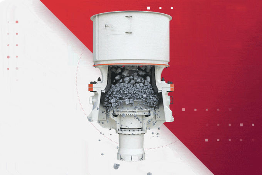
A 300 t/h secondary cone crusher that shuts down mid-shift without any visible external cause is not a mystery. In nearly every case I have investigated over two decades of field work, the failure traces back to one of seven recurring mechanical conditions — each one detectable before it becomes a production stoppage, and each one correctable without scrapping the machine. The foundational requirement is that the crusher is mounted on a concrete or structural steel base of adequate stiffness, with rubber anti-vibration pads installed between the machine frame and the foundation plinth. If that interface is compromised, no amount of component-level maintenance will produce stable operation. With that foundation verified, the diagnostic work begins.
This guide addresses each fault systematically, with the engineering parameters that define the boundary between normal operation and incipient failure. It applies whether you source your crusher wear parts from an OEM or from qualified crusher spare parts manufacturers in the aftermarket — the physics does not change based on the label on the component.
Fault 1: Lubrication Failure — Responsible for Over 70% of Premature Wear
Cone crushers operate under high specific loads — contact pressures at the eccentric bearing surface regularly exceed 8 MPa during peak crushing events — in environments contaminated with silica dust, moisture, and temperature extremes. When the lubrication film collapses at any friction interface, the resulting adhesive wear consumes component service life at a rate that can reduce the expected wear life of a cone crusher part by more than 70% compared to a properly lubricated equivalent.
Modern cone crushers use one of two thin-oil circulation systems. The first is an integral system where the oil pump is mechanically driven from the crusher’s main shaft, meaning lubrication begins only after the machine starts. The second is an independently driven lubrication unit that can pre-circulate oil through the bearing galleries before the main motor starts — a significant advantage in cold-climate operations. For machines running in ambient temperatures below 5°C, the independently driven system is strongly preferred because it allows oil to reach operating viscosity before any load is applied to the bronze bushings.
Oil temperature is the most reliable single indicator of lubrication system health. Maintain return oil temperature between 30°C and 45°C. Do not operate the crusher if return oil temperature exceeds 60°C or falls below 16°C. The control system should integrate a heater, a water-cooled heat exchanger, a return-line thermometer, and both high- and low-temperature switches to enforce these limits automatically. A crusher part supplier providing replacement lubrication system components should be asked to confirm the thermostat setpoints match the machine’s original design specification, as mismatched setpoints are a common source of subtle chronic overheating.
Fault 2: Bevel Gear Rapid Wear and Tooth Fracture
The bevel gear set — typically cut from 20CrMnTi case-hardened steel to a tooth surface hardness of 58–62 HRC — is one of the highest-stress drive components in a cone crusher. Tooth fracture is not a random event. It follows a predictable progression from pitting at the pitch line to spalling across the tooth face, accelerated by two specific assembly conditions that are both correctable.
The first condition is incorrect axial alignment between the large bevel gear and the eccentric sleeve. Field experience and manufacturing data confirm that offsetting the large bevel gear axis 2.0 to 2.3 mm toward the thin side of the eccentric sleeve — relative to the nominal concentric position — redistributes tooth contact load away from the root fillet, where fatigue cracks initiate, toward the pitch zone, where the tooth is geometrically strongest. This single assembly adjustment measurably reduces tooth fracture incidence on high-tonnage machines.
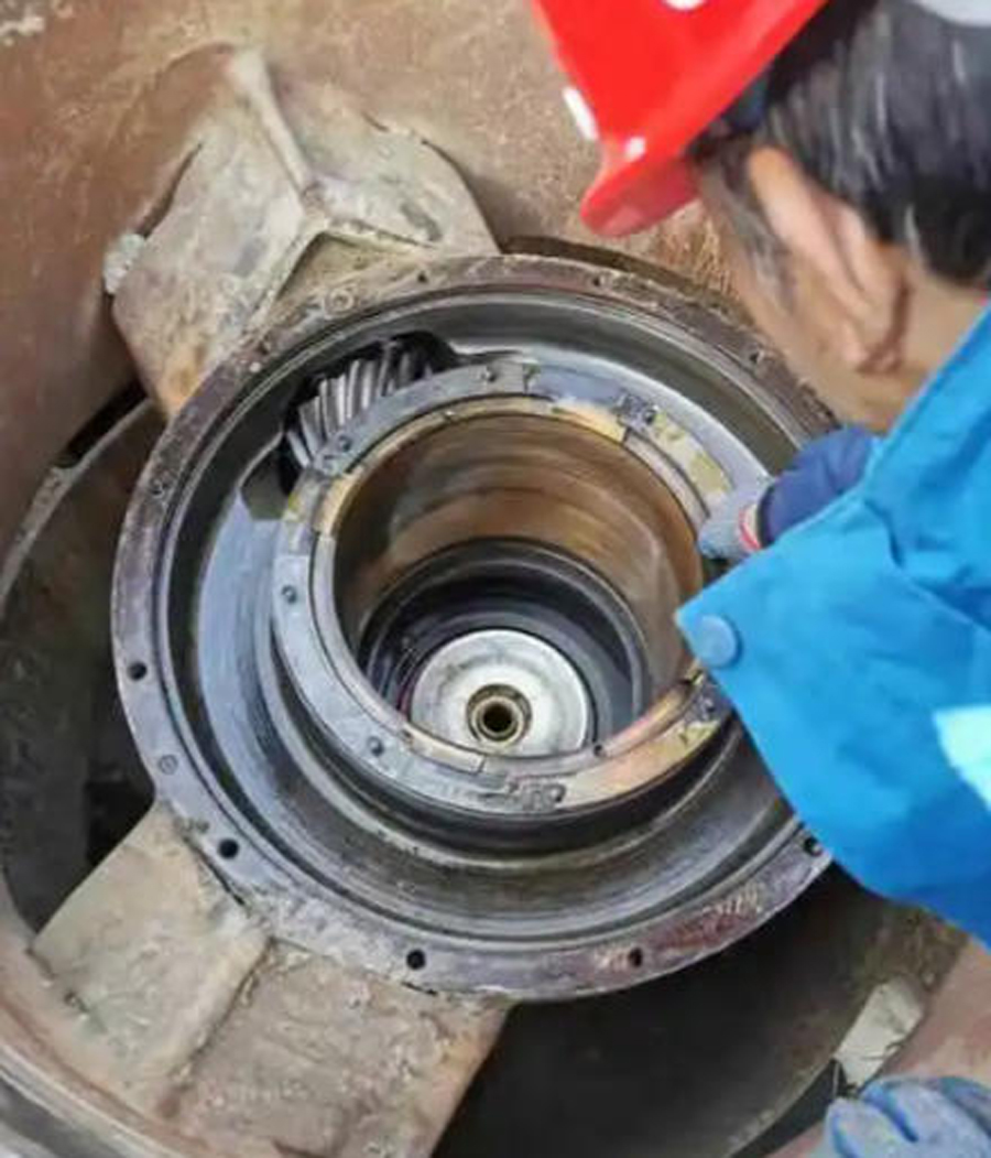
The second condition is loose fasteners at the gear mounting interface. If the mounting bolts lose preload under cyclic loading, the gear hub develops fretting at the bore, which introduces a dynamic eccentricity that causes impact loading at every tooth mesh cycle. Designing the machine base as a compliant (elastically mounted) structure with internal shock absorption, and maintaining the clearance between upper and lower housing shells within 0.25 mm, reduces the bolt preload loss rate and keeps the gear mesh geometry stable between scheduled inspections.
Fault 3: Crushing Head Lifts During Operation
When the crushing head rises off its spherical bearing seat during operation, the symptoms are immediately visible — a rhythmic upward movement of the upper frame and a distinctive impact noise at the lowest point of each eccentric revolution. The cause is almost always hydraulic pressure acting upward on the crushing head before the return oil can drain away.
In cold-weather startups, ISO VG 220 gear oil at temperatures below 10°C can have a kinematic viscosity exceeding 800 cSt — more than four times the operating viscosity — which causes the oil pump to generate pressure spikes well above the normal 0.10–0.15 MPa circuit pressure. If the pressure relief valve has drifted from its setpoint or has failed to seat correctly, this elevated pressure acts on the crushing head’s underside and lifts it. The corrective sequence is: pre-heat the lubrication oil to at least 25°C before starting; recalibrate the pressure relief valve to its specified setpoint; and if the oil pump displacement is oversized for the circuit, replace it with a correctly rated unit. These three steps resolve the vast majority of head-lifting events that crusher parts distributors incorrectly attribute to liner or bearing damage.
Fault 4: Oil Contamination Through the Water Seal — No Temperature Rise
This fault presents a confusing combination of symptoms: water appears in the drain from the water-flush seal, and oil volume in the lubrication tank gradually increases, but oil temperature remains normal. Operators frequently misdiagnose this as a cooler tube failure. The actual cause, in most cases, is a blocked return oil annular groove in the spherical bearing housing, combined with insufficient slope on the return oil drainage passage.
When the return groove is obstructed by fine ore dust or oxidized oil residue, the oil cannot drain fast enough to keep pace with pump delivery. Pressure builds in the bearing cavity, overcomes the water seal’s differential pressure margin, and forces oil into the water circuit. The fix requires cleaning the return groove mechanically, verifying the drain passage slope is sufficient for gravity drainage, and topping up the lubrication tank to the correct level after cleaning. No crusher wear parts replacement is needed — this is a maintenance access failure, not a component failure.
Fault 5: Crusher Vibration and Spring Fatigue
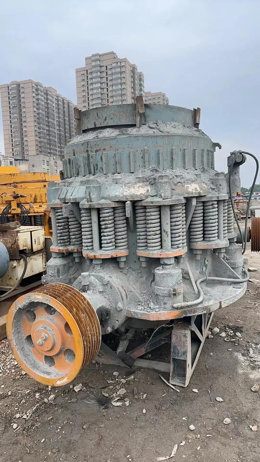
The tramp release spring assembly on a standard secondary cone crusher is pre-compressed to a clamp force of 850–1,100 kN. Springs that lose their free height within the first 500 operating hours are not defective — they are responding to an operating condition that is forcing the support ring to lift repeatedly. Repeated lifting cycles work-harden and then fatigue the spring wire, reducing the spring rate and ultimately the protection the assembly provides.
The causes of abnormal ring lifting follow a short diagnostic list: feed rate exceeds the chamber’s choke capacity; the proportion of fines in the feed exceeds 15% by mass, reducing inter-particle void space and creating hydraulic locking within the crushing chamber; feed moisture content is high enough to cause material to pack rather than flow; or the closed-side setting is below the minimum recommended for the feed gradation, forcing the machine to crush material it is not geometrically designed to handle at that setting. Correct the operating condition first. Then reset spring pre-compression to the manufacturer’s specified free height. Do not increase pre-compression beyond specification — doing so raises the effective crushing force on all bearing surfaces and converts a recoverable operating fault into a structural failure.
Fault 6: Snapping or Cracking Noise During Crushing
A sharp intermittent cracking sound from inside the crushing chamber during normal operation indicates that a liner interface has lost its load transfer continuity. Cone crusher wear parts — both the mantle (moving cone liner) and the concave (bowl liner) — are cast from Mn18Cr2 austenitic manganese steel and secured to their respective carrier components using zinc alloy (ZA-12) backfill. When this backfill cracks or separates due to thermal cycling, inadequate pour volume, or mechanical shock, the liner begins to move independently of its carrier. Each eccentric revolution produces a micro-impact between the loose liner and the steel carrier, generating the characteristic snapping noise.
Check the U-bolt clamp load on the concave first — if the torque has dropped below 80% of the specified value (typically 450–680 Nm for M36 bolts on a medium-class machine), re-torque and monitor for 6 hours. If the ZA-12 has cracked and separated, the liner must be removed, the carrier surface cleaned to bare metal, and fresh alloy re-poured. Check the head nut torque on the mantle side and inspect the pour holes to confirm full ZA-12 fill. Relying on a crusher part supplier to diagnose this remotely without torque data and pour confirmation is unlikely to produce a definitive answer — the inspection must be done physically.
Fault 7: Water in the Oil Circuit — Tank Level Rising
When water ingress raises the lubrication tank level without a corresponding oil temperature increase, the source is almost always the shell-and-tube oil cooler. The design requirement is that oil-side pressure must exceed water-side pressure at all operating points. The minimum differential is 0.05 MPa — that is, if oil circuit pressure is 0.15 MPa, the cooling water supply pressure must not exceed 0.10 MPa. When the water supply pressure exceeds this differential — due to a plant water pressure surge, a faulty pressure regulator, or a failed cooler tube — water migrates through the tube wall breach into the oil side.
Verify the water supply pressure at the cooler inlet with a calibrated gauge. If it exceeds the oil pressure by any margin, install or recalibrate a pressure-reducing valve on the water supply line. Replace the cooler tube bundle if tube-wall breach is confirmed. Oil contaminated with water must be fully drained, the tank cleaned, and fresh oil added before restarting — water-contaminated oil loses its viscosity index and film-forming capacity within hours, making every crusher wear part in the lubrication circuit vulnerable to accelerated adhesive wear.
Establishing a Maintenance Schedule: Two Methods for Determining Inspection Intervals
Preventing unplanned failures from the seven fault categories above requires a structured inspection schedule. There are two recognized approaches to setting maintenance intervals for cone crushers, and the correct choice depends on how the machine is operated.
Method One: Tonnage-Based Intervals. Inspection intervals are triggered by the cumulative mass of material processed through the crusher, expressed in metric tonnes. This method is appropriate when the machine operates at variable utilization — sometimes running at full capacity for 20 hours, sometimes at partial load for 4 hours. Because wear is driven primarily by abrasive contact, which is proportional to the mass of material processed rather than time elapsed, tonnage-based intervals align the inspection trigger with the actual wear mechanism. A crusher part supplier providing liner sets for high-abrasion iron ore will typically specify a tonnage-based change-out interval, not an hours-based one.
Method Two: Operating-Hours-Based Intervals. Inspection intervals are triggered by accumulated hours under load. This method is appropriate for machines running at consistent utilization rates on material of consistent hardness and gradation. Hours-based scheduling is simpler to administer and integrates more easily with plant-wide CMMS (Computerized Maintenance Management System) platforms.
In practice, the actual interval for any given machine is shorter than either theoretical method would predict when the feed ore is exceptionally hard (compressive strength above 200 MPa), contains a high proportion of oversize material, or is processed at consistently high utilization rates. Crusher spare parts manufacturers with genuine field experience will provide interval guidance adjusted for ore type and utilization — generic interval tables from product catalogues are a starting point, not a maintenance plan.
Major Component Inspection Reference Intervals
| Component | Inspection Type | Tonnage Trigger (soft ore) | Tonnage Trigger (hard ore, >180 MPa) | Hours Trigger (approx.) |
|---|---|---|---|---|
| Mantle (moving cone liner) | Dimensional check, profile gauge | 1,000,000 – 1,400,000 t | 600,000 – 900,000 t | 2,500 – 4,000 h |
| Concave (bowl liner) | Dimensional check, CSS verification | 900,000 – 1,200,000 t | 500,000 – 800,000 t | 2,000 – 3,500 h |
| Eccentric bronze bushing | Bore diameter, surface condition | Every 2,500,000 t | Every 1,500,000 t | 6,000 – 8,000 h |
| Bevel gear set | Backlash (target 0.25–0.45 mm), tooth surface | Every 3,000,000 t | Every 2,000,000 t | 8,000 – 12,000 h |
| Spherical bowl bearing | Clearance check (target 0.35–0.50 mm), surface finish | Every 2,000,000 t | Every 1,200,000 t | 5,000 – 7,000 h |
| Tramp release springs | Free height measurement, preload verification | Every 500,000 t | Every 300,000 t | 1,500 – 2,500 h |
| Lubrication oil sample | ICP elemental analysis, viscosity, particle count | Every 100,000 t | Every 100,000 t | 250 h (fixed) |
The intervals in the table above represent field-derived midpoints, not conservative OEM minimums. Adjust them based on oil analysis results — if iron particle concentration in the oil sample reaches 100 ppm before the next scheduled interval, pull the inspection forward. Oil analysis is the one diagnostic tool that bridges the gap between tonnage-based and hours-based scheduling, because it reflects the actual condition of the crusher parts regardless of which interval method the plant uses.
What to Demand from a Crusher Part Supplier Before the Next Scheduled Overhaul
A crusher part supplier capable of supporting a properly executed maintenance program should be able to provide, at minimum: mill certificates confirming Mn18Cr2 chemistry for all wear castings; dimensional inspection reports with tolerances traceable to ±0.05 mm; Charpy impact test values for liner castings at −20°C; and lead times short enough to support your chosen inspection interval without requiring you to carry excessive on-site inventory.
Crusher spare parts manufacturers that cannot provide chemistry documentation or dimensional inspection reports on request are selling components of unknown quality. The seven faults described in this article are expensive enough when they occur despite proper maintenance. They become catastrophic when they occur because replacement crusher wear parts introduced dimensional errors or substandard material into a machine that was otherwise correctly operated and lubricated. Specify what you need in writing, and verify it before the components go into the machine — not after the next unplanned stoppage.
| Maintenance Item | Cycle (Months) |
|---|---|
| Bowl Liner (Fixed Cone Liner) | 4–6 |
| Mantle (Moving Cone Liner) | 4–6 |
| Bevel Gear | 2–3 |
| Eccentric Bushing | 2–3 |
| Drive Shaft and Bushing Clearance Measurement | 6–12 |
| Eccentric Bushing and Straight Bushing | 4–6 |
| Main Shaft and Moving Cone | 2–3 |
| Moving Cone Assembly and Thrust Plate | 6–12 |
| Spherical Bearing and Seat | 6 |
| Adjustment Ring | 6–8 |
| Support Ring and Mainframe | 36–46 |
| Springs (Release Springs) | 6–12 |
| Eccentric Bushing and Thrust Plate | 6–12 |
| Spherical Bearing and Eccentric Bushing Upper End Face | 6–12 |
| Tapered Bushing | 2–3 |