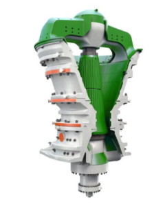

A misaligned crusher bushing found during commissioning costs one maintenance shift and a replacement part ordered from a reliable crusher parts supplier. The same defect found 600 hours into production costs a full unplanned shutdown, an emergency air-freight order, and several weeks of reduced throughput while the machine waits for rework. That distinction — drawn from more than two decades of field work on primary gyratory units across open-pit copper mines, limestone quarries, and iron ore concentrators — is the reason every measurement in this guide carries a specific number rather than a vague allowance.
Why Precision Assembly Defines the Service Life of Gyratory Crusher Parts
Primary gyratory crushers operate under peak crushing forces that commonly exceed 15,000 kN during hard-rock feed events. At that stress level, a 0.3 mm misalignment in the eccentric crusher bushing generates a bending moment that begins scoring the Babbitt lining within weeks of startup. A flange contact gap varying more than 0.5 mm around the mid-frame perimeter creates micro-movement with each crushing cycle, propagating fatigue cracks through the frame castings well before the scheduled liner change at 3,000 hours. Manufacturer tolerance specifications are not conservative suggestions — they are the engineering boundaries between acceptable wear progression and premature failure of major gyratory crusher parts.
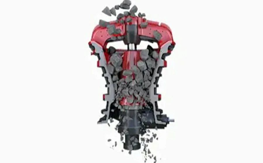
Procurement decisions affect installation outcomes in ways that remain invisible until commissioning. Gyratory crusher parts sourced from an unverified crusher parts supplier may be dimensionally within specification but metallurgically deficient. A Babbitt alloy with a tin content below 83 percent softens under the thermal loads generated inside the eccentric bushing housing, causing micro-seizure well before the standard 1,500-hour first inspection interval. Request material test certificates and hardness reports before any component reaches the assembly floor.
Lower Frame Installation — Foundation Alignment and Secondary Grouting
The lower frame is the dimensional datum for all subsequent assembly stages. Errors introduced here cannot be corrected by adjustments made higher in the machine. Begin by positioning the frame on the prepared concrete foundation and verifying levelness with a precision machinist’s level having a sensitivity of 0.02 mm per meter. Measure across all four cardinal axes of the base flange. Checking only two opposing axes is a common oversight that misses diagonal tilt entirely and results in eccentric shaft runout that no bushing clearance adjustment can compensate for later.
A gap of not less than 30 mm must be maintained between the underside of the base plate and the foundation surface before secondary grouting begins. This clearance allows the non-shrink grout compound — typically an epoxy or cementite formulation with a minimum 28-day compressive strength of 35 MPa — to flow freely beneath the full base area and eliminate all voids. Pre-tension anchor bolts to 30 percent of the final specification torque before pouring grout. After the grout achieves full cure, a minimum of 72 hours at ambient temperatures above 10 degrees Celsius, retighten all anchor bolts in a cross-pattern sequence to full torque, generally between 800 Nm and 1,200 Nm for primary gyratory frames in the 54-75 size class.
Verify levelness again after final bolt torque is applied. Solar heating during summer commissioning campaigns can shift a base plate by 0.1 to 0.2 mm relative to its pre-grout position. This deviation must be confirmed within tolerance before the mid-frame is lowered onto the assembly.
Transmission Assembly and Crusher Bushing Alignment in the Drive Housing
Two bronze transmission bushings support the pinion shaft inside the drive housing. Their centerlines must share a common horizontal axis, with permissible radial deviation not exceeding 0.05 mm across the full span between bushings. Any offset beyond this tolerance creates a bending moment on the pinion that accelerates fretting wear on both the crusher bushing bores and the shaft journal surfaces, reducing the effective replacement interval by up to 40 percent compared to a correctly aligned assembly.
Radial clearance between the crusher bushing bore and the shaft journal must be measured with a dial bore gauge before the housing is closed — never estimated from nominal dimensions alone. For primary gyratory pinion shafts in the 180 mm to 280 mm diameter range, the specified clearance typically falls between 0.15 mm and 0.35 mm. Below 0.15 mm, thermal seizure occurs during high-load cold starts. Above 0.35 mm, the hydrodynamic oil film breaks down under impact loading, and metal-to-metal contact scoring begins within 200 to 400 operating hours. Both failure modes are field-preventable through correct measurement at installation.
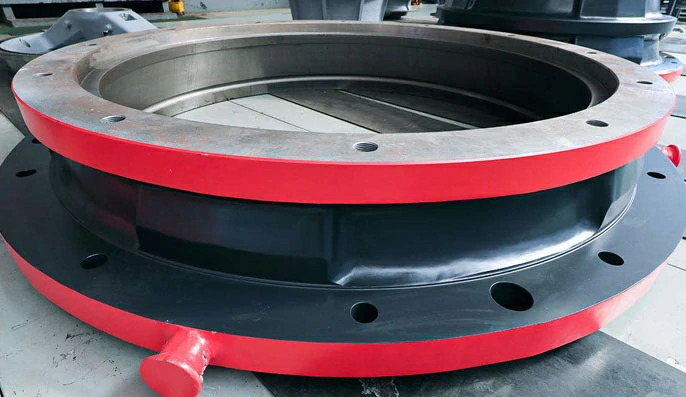
Shims placed between the drive housing flange and the main frame control the bevel gear mesh position. The bevel gear tooth tip clearance must meet the design specification, typically 1.5 mm to 3.0 mm depending on gear module. A mesh deviation of even 0.5 mm introduces an axial force component that the crusher bushing housing was not designed to carry, and the resulting asymmetric wear pattern becomes visible as a tapered score on the bushing bore within 2,000 operating hours.
Eccentric Bushing Installation — The Highest-Stakes Stage in Gyratory Assembly
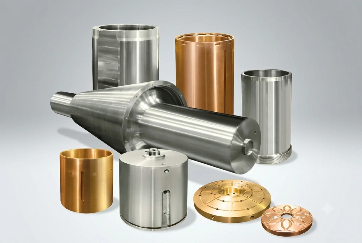
The eccentric crusher bushing is the most precision-sensitive component in the gyratory system and among the most expensive gyratory crusher parts to replace under field conditions. Its inner and outer Babbitt-lined surfaces must arrive at the installation site with their lapped finishes entirely intact. A surface scratch deeper than 0.01 mm on the Babbitt layer creates a stress concentration that initiates spalling under the oscillating hydrodynamic pressure of the lubrication film during normal operation.
Before fitting the bushing, inspect both Babbitt surfaces under oblique lighting for scoring, pitting, and casting porosity. Measure the outer diameter of the eccentric bushing and the housing bore with an inside micrometer at a minimum of four axial positions and three circumferential positions around each cross-section. The interference fit between the eccentric bushing outer diameter and the housing bore should fall within 0.04 mm to 0.12 mm for standard gyratory eccentric housings. Below 0.04 mm, the bushing rotates in the bore under load. Above 0.12 mm, the press-fit crushes the Babbitt on the outer diameter surface — damage that cannot be recovered by field scraping or re-lapping and that necessitates a full bushing replacement.
After the eccentric assembly is pressed into position, re-verify the bevel gear tooth tip clearance, since the press operation can shift the vertical datum by a measurable increment. Correct any deviation through adjustments to the shim stack. Never attempt to correct clearance by re-pressing the bushing; a second press operation on a fitted bore almost always compromises the Babbitt surface integrity and defeats the purpose of precision assembly entirely.
Mid-Frame Installation — Contact Tolerance and Pin Seating Protocol
Before lowering the mid-frame onto the lower assembly, clean all four tapered contact surfaces around the flange perimeter and inspect for raised spots, corrosion deposits, or machining burrs. The gap between mating flange surfaces must be uniform, with maximum variation of 0.5 mm around the full 360-degree perimeter. Variation beyond this limit indicates a distorted lower frame flange, a casting defect in the mid-frame, or contamination on the mating faces. Do not proceed until the source of non-uniformity is identified and corrected.
The designed axial gap between upper and lower frame interface surfaces is approximately 15 mm after the mid-frame is fully seated. This gap must be uniform in depth around the perimeter. On a machine with a 1,500 mm mantle diameter, a 1 mm tilt at the mid-frame joint produces approximately 3 mm of eccentric runout at the mantle rim — far outside the operating tolerance for any production gyratory and sufficient to overload the eccentric bushing on the high side of each rotation within the first few hundred hours of service.
Drive each dowel pin firmly at initial assembly. After the first 4 to 8 hours of production load, re-inspect and re-drive all pins. Thermal cycling during the break-in period causes micro-settling at the joint, and pins confirmed tight at cold installation can show 0.1 to 0.2 mm of axial travel after the first thermal cycle. Achieving uniform final pin seating distributes radial shear load equally across all pins and prevents progressive joint rotation under the eccentric loading pattern that is inherent to gyratory crusher operation.
Crushing Cone and Crossbeam — Two Validated Assembly Sequences
Two field-validated sequences are used for installing the crushing cone and crossbeam as the final stage of gyratory crusher parts assembly. The selection between them depends on site-specific crane access, assembly pit availability, and total lifting capacity at the installation location.
| Comparison Factor | Sequence A — Cone Installed Independently | Sequence B — Pre-Assembled Cone and Crossbeam |
|---|---|---|
| Number of crane picks | 2 sequential picks | 1 combined pick |
| Grade-level assembly pit required | Not required | Required |
| Single pick lift weight (54-75 class) | Lower per individual pick | 18,000 kg to 32,000 kg combined |
| Preferred site condition | Unrestricted overhead crane access | Restricted crane access above crusher |
| Pre-lift inspection access | Limited during individual cone lift | Full access at ground level before the lift |
Sequence A — Independent Cone Installation
Attach a certified mainshaft lifting eye to the upper threaded section of the crushing cone. Lower the assembly through the spider and into the frame. Place hardwood cribbing blocks on the lower frame ribs to temporarily support the cone body from below. With the cone cribbed securely in position, install the crossbeam into the spider arms, fit the mainshaft upper nut and outer sleeve, then secure the cap. Remove all cribbing blocks and wedges only after all upper fasteners have been brought to final torque specification and verified with a calibrated torque wrench.
Sequence B — Pre-Assembled Cone and Crossbeam
Complete the crossbeam-to-cone sub-assembly in a dedicated pit at grade level, where access conditions allow thorough torque verification and contact surface inspection before the combined lift. When rigging the pre-assembled unit for the crane pick, attach wire rope slings to the crossbeam structural members — never to the mainshaft threads or the mantle surface. The combined weight of the crossbeam and crushing cone on a 54-75 primary gyratory typically falls between 18,000 kg and 32,000 kg. A formal rigging plan reviewed by a certified rigging engineer is mandatory for any lift in this weight range.

Regardless of the sequence chosen, the mantle must be firmly and fully seated against the head center before the upper locking nut is brought to final torque. A partially seated mantle generates a high-cycle impact load at every crushing stroke. The resulting fatigue damage initiates cracking at the mantle-to-head interface within 300 to 500 operating hours. Before pressing the mantle into final position, coat the locking thread and the underside of the fixed ring thoroughly with a heavy lithium-based grease rated for continuous service above 120 degrees Celsius. This treatment prevents thread corrosion and galling between scheduled mantle changes, which typically occur between 1,500 and 4,000 operating hours depending on the abrasivity index of the ore being processed.
Evaluating a Crusher Parts Supplier Before Assembly Begins
Precision installation protocol only delivers its intended outcome when the gyratory crusher parts being assembled meet both dimensional and metallurgical specifications. Selecting a crusher parts supplier must therefore be completed and verified before any component ships to the installation site — not resolved after an installation defect triggers a warranty dispute or a production shutdown. When evaluating any crusher parts supplier, confirm performance across the following areas before placing a purchase order.
- Dimensional inspection reports should confirm critical bore diameters, interference fit surfaces, and Babbitt layer thicknesses to within 0.01 mm tolerance bands for every crusher bushing supplied. Nominal dimension claims without supporting measurement data are insufficient for precision gyratory components.
- Metallurgical certificates for Babbitt-lined components must specify tin content, antimony content, and copper content by mass fraction, along with the minimum as-cast hardness of the alloy after aging treatment. A certificate that lists only a trade name or grade designation without elemental composition is not acceptable.
- Lead time commitments for high-criticality gyratory crusher parts — eccentric bushings, mantle assemblies, and spider cap bushings — must be confirmed in writing before procurement is finalized. A 16-week lead time on a critical bushing can idle a 50,000-tonne-per-day operation for far longer than any installation tolerance violation would have caused.
- Field support availability — the ability of the supplier to dispatch a qualified technical representative for commissioning inspection — distinguishes a long-term supply partner from a transactional parts vendor and is worth factoring into the total cost of ownership calculation.
Installation as the Foundation for Reliable Long-Term Crusher Operation
Large primary gyratory crushers do not forgive casual installation practices. A 20-tonne crushing cone assembly, a bevel gear set transmitting thousands of kilonewtons of load, and a crusher bushing running at hydrodynamic oil film thicknesses measured in hundredths of a millimeter — all of these demand the same methodical attention to specification compliance from the first anchor bolt to the final mantle press. Work systematically, verify dimensions at each stage before advancing to the next, and involve the equipment manufacturer’s field service team at every step that carries a dimensional consequence for subsequent assembly stages.
The installation sequences and parameter ranges described throughout this guide reflect general field practice for primary gyratory configurations and serve as a technical reference to be used alongside — never as a substitute for — the manufacturer’s specific installation manual for the unit being commissioned. Exact tolerances, torque values, and assembly sequences differ between machine models, size classes, and regional design variants. When the manufacturer’s documentation and general field guidance conflict, the manufacturer’s documentation for that specific unit takes precedence without exception.