

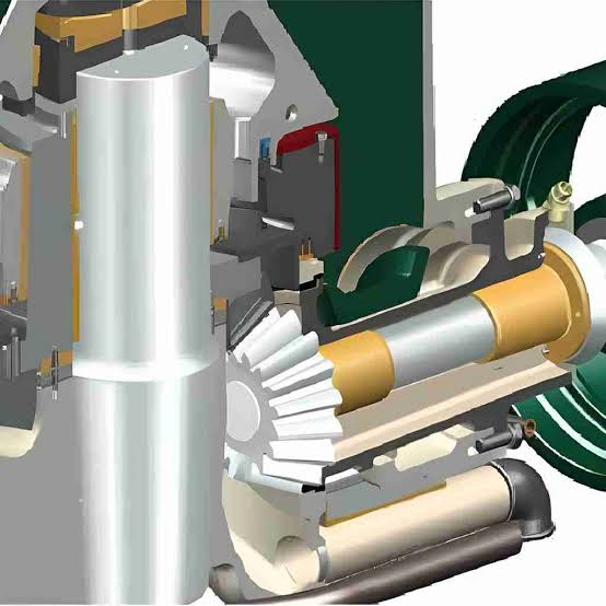
A countershaft that starts humming at a slightly higher pitch during idle rotation is usually not a bearing problem, it is a bushing clearance problem, and by the time that pitch change is audible from the platform, the running clearance has often already opened up beyond the 0.15 mm design limit. On a GP500 cone crusher, this single component sits between the drive motor’s torque input and the eccentric assembly that drives the entire crushing action, and when the countershaft bushing wears past tolerance, the resulting radial play translates directly into erratic crushing chamber movement, uneven liner wear, and eventually a snapped drive key or a scored shaft that costs far more than the part itself to correct. This is precisely why cone crusher parts like the countershaft and its bushing deserve the same engineering scrutiny as any structural casting, not just a parts-catalog lookup. The following breakdown covers the full specification of the Metso GP500 countershaft, designated G15, along with its mating bushing, for engineers managing spare parts inventory or planning a mid-life rebuild.
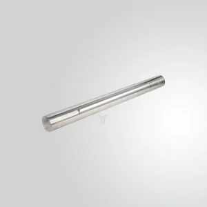
Product Parameters
| Parameter | Specification |
|---|---|
| Applicable Model | Metso GP500 Cone Crusher |
| Part Designation | Countershaft, G15 |
| Component Weight | 109.2 kg |
| Manufacturing Process | Forged alloy steel, normalized and tempered |
| Base Material | 42CrMo4 / AISI 4140 equivalent forged steel |
| Journal Diameter (Bushing Contact) | 135 mm ± 0.02 mm |
| Overall Shaft Length | 820 mm |
| Core Hardness | 28 HRC – 32 HRC |
| Journal Surface Hardness | 52 HRC – 58 HRC (induction hardened) |
| Case Depth (Induction Hardened Zone) | 2.5 mm – 3.5 mm |
| Surface Roughness on Journals (Ra) | 0.4 μm – 0.8 μm |
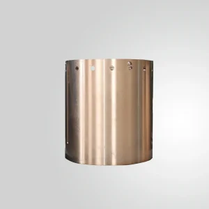
| Countershaft Bushing Material | Bronze alloy (SAE 660 / C93200 equivalent) |
| Bushing Wall Thickness | 8 mm nominal |
| Design Running Clearance | 0.08 mm – 0.15 mm |
| Maximum Allowable Clearance (Wear Limit) | 0.35 mm before mandatory replacement |
| Drive Pulley Bore Fit | H7/k6 interference fit |
| Keyway Dimension | 32 mm x 18 mm, DIN 6885 standard |
| Retaining Bolt Torque (Bearing Housing) | 420 N·m ± 5% |
| Nut Torque (Drive End Locknut) | 650 N·m ± 5% |
| Balance Grade | G6.3 per ISO 21940 |
| Non-Destructive Testing | Magnetic particle inspection on journals and fillet radii |
| Quality System | ISO 9001 certified manufacturing, dimensionally verified against OEM drawing |
Why Countershaft Wear Drives Cone Crusher Downtime
Cone crusher parts operating in the drive train experience a very different failure mechanism than crushing chamber wear liners. The countershaft does not wear from abrasive rock contact, it wears from cyclical torsional loading and the constant radial force transmitted through the bevel gear mesh into the eccentric shaft. On a GP500, the countershaft rotates at speeds typically between 1,000 and 1,200 rpm depending on eccentric throw configuration, meaning the journal surfaces at the bushing contact points endure roughly 60,000 to 72,000 load cycles per hour of operation. This is why the journal diameter tolerance is held to ±0.02 mm and why the induction-hardened case depth on the journal surface, typically 2.5 mm to 3.5 mm, matters more for long-term reliability than most buyers initially appreciate. A shaft with an undersized case depth will wear through the hardened layer prematurely, exposing the softer core material and accelerating clearance growth well before the rated service interval.
Material Composition Analysis
The shaft and bushing pairing uses two deliberately different material families, and understanding why matters for anyone specifying replacement cone crusher parts.
| Element | Forged Shaft 42CrMo4 (%) | Bushing Bronze SAE 660 (%) |
|---|---|---|
| Carbon (C) | 0.38 – 0.45 | — |
| Chromium (Cr) | 0.90 – 1.20 | — |
| Molybdenum (Mo) | 0.15 – 0.30 | — |
| Manganese (Mn) | 0.60 – 0.90 | — |
| Copper (Cu) | — | 83.0 – 87.0 |
| Tin (Sn) | — | 6.3 – 7.5 |
| Lead (Pb) | — | 4.0 – 6.0 |
| Zinc (Zn) | — | 2.5 – 4.0 |
| Yield Strength | 650 MPa min | 125 MPa |
| Tensile Strength | 850 – 1000 MPa | 240 MPa |
The forged 42CrMo4 shaft material is chosen for its combination of core toughness and its response to induction hardening, allowing the journal surface to reach 52-58 HRC while the shaft core stays ductile enough to absorb torsional shock without brittle failure. The bronze bushing, by contrast, is intentionally the softer of the two mating surfaces, because in any properly designed shaft-bushing pair, wear should concentrate in the low-cost, easily replaceable bushing rather than the far more expensive forged shaft. The tin and lead content in the SAE 660 bronze provide self-lubricating properties under boundary lubrication conditions, which matters during startup before full oil film pressure develops.
Field Installation Guidance
- Measure the existing bushing bore and shaft journal diameter with a micrometer before ordering; running clearance exceeding 0.35 mm confirms both shaft and bushing require replacement, not the bushing alone.
- Heat the bushing housing to approximately 80°C before pressing in a new bushing to achieve proper interference fit without scoring the bore surface.
- Align the countershaft using a dial indicator against the drive pulley face; runout should not exceed 0.05 mm at the pulley outer diameter.
- Torque the bearing housing retaining bolts to 420 N·m in a cross pattern, then verify with a follow-up pass after the first 24 hours of running-in.
- Apply the specified locknut torque of 650 N·m only after confirming correct bearing preload, since over-torqueing at this stage is a common cause of premature bearing failure.
- Check keyway fit for the drive pulley before final assembly; excessive play in the 32 mm x 18 mm keyway is a frequent root cause of cyclic shaft loosening in the field.
Preventive Maintenance Recommendations
Preventive maintenance for this class of cone crusher parts centers on tracking clearance growth rather than waiting for audible symptoms.
- Measure countershaft bushing clearance every 2,000 operating hours using a dial bore gauge, and flag any reading approaching 0.25 mm for scheduled replacement planning.
- Sample lubricating oil quarterly and check for elevated copper and tin content, which indicates accelerating bushing wear well before mechanical symptoms appear.
- Inspect the drive pulley keyway annually for fretting corrosion, a common early indicator of cyclic micro-movement caused by loosening clamping force.
- Monitor vibration at the countershaft bearing housing monthly, since a rising trend in the 1x running speed frequency band typically correlates with growing bushing clearance.
- Log torque values at every scheduled inspection for the locknut and bearing housing bolts, since gradual torque loss over time is a leading indicator of joint fretting.
Field Notes From Twenty Years on the Crusher Deck
I have replaced countershaft and bushing sets on GP500 units more times than I can count, and the failures that cost operations the most are almost always the ones where someone tried to stretch the bushing life past the 0.35 mm clearance limit to avoid a shutdown. On one aggregate operation, the maintenance team pushed a worn bushing for an extra six weeks because the shaft “still sounded fine,” and by the time they finally pulled it, the journal surface had scored deeply enough that the shaft itself needed replacement instead of just the 109.2 kg countershaft casting they had budgeted for. That single decision turned a scheduled four-hour bushing swap into a nineteen-hour emergency shutdown with a shaft on backorder. My rule since then, and one I recommend to every site I consult for, is simple: measure clearance on a fixed interval, not by ear, and never let a countershaft bushing run past 80% of its rated wear limit regardless of how the machine sounds.
Frequently Asked Questions
How is dimensional accuracy verified on a replacement GP500 countershaft before shipment?
Every forged shaft is measured on a coordinate measuring machine against the original OEM drawing, with particular attention to journal diameter tolerance and keyway alignment, and magnetic particle inspection is performed on fillet radii to rule out forging defects before final machining is approved.
What packaging and transport precautions apply to a 109.2 kg countershaft shipment?
The shaft is shipped with journal surfaces wrapped in rust-preventive film and rigid end caps to protect the induction-hardened zones from impact damage, and it is crated with foam block supports to prevent shifting during transit, since any dent or scratch on the hardened journal surface voids the fit tolerance.
Does the countershaft warranty cover bushing wear, and what documentation is needed for a claim?
The forged shaft carries a material and machining defect warranty, but bushing wear is a consumable item excluded from long-term warranty coverage, so any claim on the shaft itself requires documented clearance measurements and lubrication records showing the bushing was replaced within the recommended interval.
Reviews
There are no reviews yet.